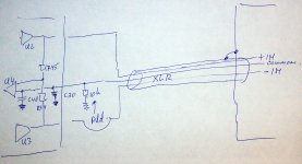
I am not an expert of servos and I might not understand the way you intend to use that circuit (maybe here a drawing could help) but, if I am understanding right by connecting the input to GND, you are actually using a differential amplifier to sense the common mode ouput offset and injecting it back to the stage.
If my understanding is correct, then I am afraid that the authority of this servo control could be way to high to not only influence very low frequencies but a higher badwidht causing perhaps suppression of musical signal as well.
My two cents and I could be wrong f so, please explain.
Like in the picture, it would not fight AC differences between source and destination equipment, only DC (but I did read some ware, I think it was one of dself's books, that this can/will be helpful).
Attachments
Cool to invent a cartridge with a center-tap.... Who will you find to build it for You....??
Or do I misunderstand your schematic..???
The LTP has a common reference so you can use the cartridge floating....
Here is a possible revision of that.
Now the they are both referenced to the same poin LTP's style.
MasterPiece-R4
When do we want to start evaluating the prototype? I wuold like to know if we are all ok with the schematic or we feel that improvements should be made (perhaps Servo?).
Attachments
Only you can decide that. I would build it and learn in the process.
yeah for sure, I will try to build it in the next couple of days or maybe sooner.
But what do you think overall about the schematic?
Would you do it differently?
I thought we were having a joint like on the paradise where a lot of ideas were thrown in, evaluated, perfected and so on....and not only me... which I am most of the time dumb and have a just this little knowledge and experience compared to the monsters here
")
If you guys have the desire just like me to build something meaningful a balance phono stage then let's start working more as a team.....I don't know if my point comes across.....
Sure, i needed 3 years until SOME took me serious. Patients is extremely important when you want to do something outstanding like you plan. By the way the Paradise R3 needs the elcaps because the input stage is BJT. With BJts you need to separate the bias. J-Fets do not need that. So at least one attempt to answer that question.
you are right Joachim afterall I am alredy glad that few people so far are partecipating!
For the ElCap, thanks for the explanation it makes sense.
Masterpiece R-4's prototype is almost ready...hopefully I will be completing it tonight and start making some measurements and listening tests tomorrow.
For the ElCap, thanks for the explanation it makes sense.
Masterpiece R-4's prototype is almost ready...hopefully I will be completing it tonight and start making some measurements and listening tests tomorrow.
You are very fast, Stefanoo. I wish you success.
We are already at post 108, so i think you get good attention. When the circuit works it will get even better. Many people here are more practical and not so interested in details of the topology. I would contribute more but i am too busy at the moment.
We are already at post 108, so i think you get good attention. When the circuit works it will get even better. Many people here are more practical and not so interested in details of the topology. I would contribute more but i am too busy at the moment.
You are very fast, Stefanoo. I wish you success.
We are already at post 108, so i think you get good attention. When the circuit works it will get even better. Many people here are more practical and not so interested in details of the topology. I would contribute more but i am too busy at the moment.
I understand...don't worry...whenever you have little more time...then...feel free to throw in your 10 cents
I "unfortunately" work full time as well....so I can't complete it as fast as I would like to...
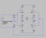
Significant update to MasterPiece, servo now has been simplified due to the reference point of the sources on both halves to GND through the same resistor.
Conceptually works and so does in simulation. I will have to make sure it works on the prototype as well as soon as I have that up and running.
Here is the schematic MasterPiece-R5
Conceptually works and so does in simulation. I will have to make sure it works on the prototype as well as soon as I have that up and running.
Here is the schematic MasterPiece-R5
Attachments
Looks good. When it works in simulation it should work in praxis too.
Thank you very much.
Once it is implemented I will post spectral density's measurements, frequency accuracy and distortion measurements.
Significant update to MasterPiece, servo now has been simplified due to the reference point of the sources on both halves to GND through the same resistor.
Conceptually works and so does in simulation. I will have to make sure it works on the prototype as well as soon as I have that up and running.
Here is the schematic MasterPiece-R5
I like the fact that it now has a s single servo, but be aware
If one side (of the diff amp) has an offset different from the other side it will set one side to -((offset(left)-offset(right))/2) and the other side will be set to +((offset(left)-offset(right))/2). To prevent this you need to be able to set the static-offset-difference to zero (volts difference between left and right side).I had that problem if you have a feedback resistor connected between the two halves you will get a common mode offset and it is nearly impossible at this gain to have a 0 differential and absolute offset by trimming the absolute.
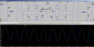
And this can be proven on the simulation by unbalancing the two halves i.e. superimposing a different offset among the two sides.
So using the differential configuration carried on in the previous version, would slam the differential output two 0 and the absolute to a certain value that can be trimmed down to 0 acting on the house keeping current source's section.
In this arrangement however, simulation proves that not only the differential offset is 0 for whatever unbalancy you have, but so is the absolute.
If you think true, this is conceptually correct as on both sides the souces are now connected to the same potential generating a common mode voltage to correct will equally correct both of them and since the integrator is pointing at 0 thus the output voltage will be corrected to 0V.
I will post simulation results to support this statement.
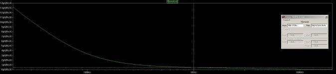
Here it is:
As you can see I have deliberately made the two side very different in terms of output offset however both sides are corrected down to 0.
In the first versions I would have gotten with this configuration a common mode offset.
In this arrangement, things change, take a look here.
Simulation seems to be set up properly thus I would hope that this is going to reflect the reality as well.
Attachments
Here it is:
As you can see I have deliberately made the two side very different in terms of output offset however both sides are corrected down to 0.
In the first versions I would have gotten with this configuration a common mode offset.
In this arrangement, things change, take a look here.
Simulation seems to be set up properly thus I would hope that this is going to reflect the reality as well.
I'm not (yet) totally convinced, would you do the same simulation with both side a negative start offset (not one positive and the other negative). Already it looks better than I expected
maybe I should have given it a bit more time (but I do not have that much of it (time) ).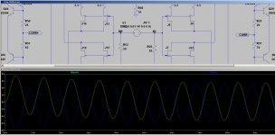
- Status
- This old topic is closed. If you want to reopen this topic, contact a moderator using the "Report Post" button.
- Home
- Source & Line
- Analogue Source
- Masterpiece