Stafanoo,
Thanks for the answer. Yes I will follow this as much as I can but I would say that just having a schematic is only part of the puzzle. Without a competent circuit board layout you and all of us should know you will not achieve the desired results. Just saying that it will take more than just the schematic to get your results in the end product.
Steven
I my opinion the sources have to be referenced to ground too. Otherwise i can not help and you have to find out why it is so noisy yourself.
Is this what you have in mind?
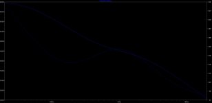
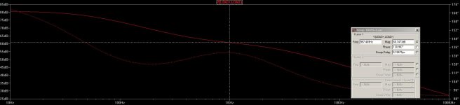
Frequency response with Filter attached.
I can protoype it with this values and take measurements and post in here the results. If thad is what you were thinking, do you want me to measure it without the filter fitted and only the gain setting resistance on the TransZ or with filter in it?
Would this help development or you still feel we need to make adjustments to it or this is a good starting point?
If the schematic is not what you had in mind please let me know...
Attachments
Stefano, the noise goes from gate to source and then though the 100 Ohm to ground. Assuming that R1, R26 are parallel AC wise you end up with 1nV/qHz only from this resistors. It is an improvement over R1 but still not very impressive. You should at least shoot for 0.5nV/qHz, that is 6dB better. My best stages are around 0.3nV/qHz so even 4.5dB better then 0.5nV/qHz.
For some reason it looks like I can't make them any lower on simulation or the gain will just drop.
I usually set that resistor down to 10ohm or less..however for some reason it looks like I can't do that here.
Any clue? Maybe if I lower the resistor that sets the gain on the trans Z network I can re-establish proper gain. However if I change that value I will likely have to re-design the RIAA 's circuit which it would be ok anyway.
I will work on it and post later tonight!
Think Joachim wrote it before "floating" is not "balanced" you try to make two independent circuits behave like like they were one. but you cant cause they have no common reference. In order to make this you have to have a common reference circuit like in an LTP. Or you could build a cartridge with a center tap...")
I like the center tap's idea better !! Speaking if which..this might be a good moment to throw this in: is a cartridge true balance source? IMHO if it hat the CT it would but since it doesn't is it really.
I still don't understand, have I answered to Joachim with schematic R2.
If not, feel free to mark that up and I will get that into the official's file.
It's a little late here now, time to relax for me too
!! Speaking if which..this might be a good moment to throw this in: is a cartridge true balance source? IMHO if it hat the CT it would but since it doesn't is it really.I still don't understand, have I answered to Joachim with schematic R2.
If not, feel free to mark that up and I will get that into the official's file.
It's a little late here now, time to relax for me too
A cartridge is a floating source. Nevertheless a balanced input makes some sense to suppress common mode noise and it suppresses 2nd harmonic.
And, the cartridge is disconnected from ground, so ground artifacts, like hum, and radio-wave induced signals, where the connection wire or the tone-arm is the antenna, are largely/partly avoided, and this can be heard/measured.
Joachim/all,
this is the latest scheatic for MasterPiece.
I had to re-arange the Servo into 2 separate ones and at taht point I was able to lower the Feedback resistors down to a very low noise approach and boost up the gain and reach 61dB with the single stage.
It looks like we could possibly get rid of the bootstrap caps using the arrangement shown here (please feel free to comment on pro and cons if there are any).
I am still not sure how it works in SE as it looks like the gain would drop down by 6dB on the Bal version in SE mode and how this can be re-arranged on the SE Paradise as the common mode resistors allows to set an AC path between the two halves boosting up the gain (also corrects a little bit asymmetries of the two parts thus lowering ditortion).
What do you think about this schematic? Is this what you had in mind?
As you can notice I have also halved the number of paralled Jfets which would increase gain another few dB eventually, but I think there could be sonical benefit by keeping this number down to the minimum required.
Attachments
Please FwD and others here, if you could mark up on a simple sketch how you think the cartridge has to be connected in balance mode to minimize ground loops and radio signal from getting into the path, plase go ahead and I will re-arrange the schematic accordingly.
Thanks.
Thanks.
Please FwD and others here, if you could mark up on a simple sketch how you think the cartridge has to be connected in balance mode to minimize ground loops and radio signal from getting into the path, plase go ahead and I will re-arrange the schematic accordingly.
Thanks.
I’m not too fond about the two servo’s. Let’s see what they do, as this is a mirrored symmetrical design, I would think that the offset on both side will be the same (with respect to temperature). May be a small static adjustment could be introduced to set both offsets to the same value. Have a look at http://www.cirrus.com/cn/pubs/whitePaper/aes04.pdf figure 2, a setup like this (replace the 2 opamps in the signal path with the output buffers as being used (or some like them)) could be used to annihilate any offset that appears on the output connectors.
You asked
are you referring to the U4 on page 10? If so I can't find where Vcm is sourced from.
are you referring to the U4 on page 10? If so I can't find where Vcm is sourced from.
Yes, I am
As I see it, Vcm can be sourced from (local) ground, or it can be sourced from (remote) ground (when connected to a balanced input, then the ground at the other side should be used), this would be my preference. When used to connect (remote) ground, then I would connect it to (local) ground with a 10Kohm resistor (in parallel so to say).
I am not an expert of servos and I might not understand the way you intend to use that circuit (maybe here a drawing could help) but, if I am understanding right by connecting the input to GND, you are actually using a differential amplifier to sense the common mode ouput offset and injecting it back to the stage.
If my understanding is correct, then I am afraid that the authority of this servo control could be way to high to not only influence very low frequencies but a higher badwidht causing perhaps suppression of musical signal as well.
My two cents and I could be wrong f so, please explain.
If my understanding is correct, then I am afraid that the authority of this servo control could be way to high to not only influence very low frequencies but a higher badwidht causing perhaps suppression of musical signal as well.
My two cents and I could be wrong f so, please explain.
Honest, i would make a long tail pair input ( several in parallel ), that would solve a lot of problems.
What problem would it solve to you besides having only a n-ch fet?
- Status
- This old topic is closed. If you want to reopen this topic, contact a moderator using the "Report Post" button.
- Home
- Source & Line
- Analogue Source
- Masterpiece