http://home.tele2.at/alohka/page3.gif
I gave out all you have to know about the OPA1632 stage.
No, i will not detail that circuit to any higher degree.

That is the deal, no spoon feeding, sorry.
But there is everything.
It should not be to hard to make it work. I do not even think that it is particular genial, innovative, amazing or anything. It is just a way to make good use of that super Fets.
It is simple and clean basically and does the job very well. It is one of these things where you can not take anything away or it does not work any more.
Looking at it, I really think this servo is intrusive.
Basically it corrects right at the input of a 60-65dB normalized gainstage.
Plus the use of the 1m right at the input seems excessive.
Isn't there any different way to correct it?
I am also thinking how much the differential offset will wonder if the stage is built with monolithic BJTs.
Also like I said the differential offset can be corrected between the two legs of the differential input but I was unable to find a suitable circuitry for that.
I am really curious to see what the other alternatives you have in mind are
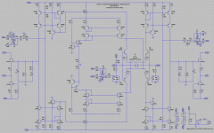
Intrusive or not, this is my (most probably the only possible servo-ed solution) for the input differential. The big 1mF elcaps are there to keep the low (100 Ohm) ground reference as is in the original schema for AC. For DC the parallel resistor of 100 Ohm gives the servo some room to do its work.
I would say, take it or leave it, this is what I think is a good solution, if you have a better one, then show it.
P.s. I really fail to see what the significance of the term 'intrusive' is in this context. With regards to the DC offset, the servo is (near) 100% intrusive (as intended). With regards to the AC (audio signal), the servo is totally non intrusive (for frequencies above the FT of the servo).
I am really curious to see what the other alternatives you have in mind are
The mirror just before the output buffer can be influenced to control the output DC offset. This can be done separately for the Out+ en Out- side of the RIAA. Controlling the mirror can best be done by using some form of current injection, that is controlled by a servo.
After giving this a bit more thought, I come with this for input differential nulling. The previous scheme will not work, the input differential was null due to the fact that the cartridge-model had a series resistance of 0 Ohm (a bikini model would have been just as effective). I upped the series resistance of the cartridge to 50 Ohm and added some offset injection (R58) for testing. This version will work.
For output offset nulling I still have no final scheme, those guys from ATL where not as smart as it seems
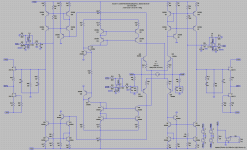
And here is the completely servo-ed pre-amp. I'm sure the values can/may change, but the principle's are 'sound'
Note that R34 and R28 are not needed (and should be removed Also the opamps need a separate +- 15V supply. Also I like to add some sort of servo output filter to slow it down and do some additional servo noise removal, this is not strictly needed.Attachments
Last edited:
And here is the completely servo-ed pre-amp. I'm sure the values can/may change, but the principle's are 'sound'
P.s. I did forgot to take out the offset generator R58

In that case, you might like this.
(old schematic btw, revision of ~dozen years ago, beauty of opamps is that they reduce to simple Lego blocks in experimental stages. the Pope of Rock & Rolla isn't the only one who jumps Double-Dutch)
Attachments
Last edited:
Frans ... very very clever with the servo injection after the input stage in the current mirror, this will actually keep the input offset very very low and still correct the output, one may argue that they are in the signal path, but then again what servo is not.... This circuit can be very very good, only one thing needs to be done regarding the RIAA section.. two set of components must be reduced to one, which on the other hand should be pretty straightforward.
This circuit can be very very good, only one thing needs to be done regarding the RIAA section.. two set of components must be reduced to one, which on the other hand should be pretty straightforward.Frans ... very very clever with the servo injection after the input stage in the current mirror, this will actually keep the input offset very very low and still correct the output, one may argue that they are in the signal path, but then again what servo is not....
Thank you, you made my smile
Frans ... very very clever with the servo injection after the input stage in the current mirror, this will actually keep the input offset very very low and still correct the output, one may argue that they are in the signal path, but then again what servo is not....
yeah reducing the RIAA to one would be very desirable, but how?
Well, the servo on the SE version is not on the signal path directly, while the one for the differential is right at the input.
Don't know at the end of the day it is good as long as it sounds good, so it will have to be tried.
Should I take charge and try it out?
Watching and waiting for the final version of this design. I hope someone will take that an do the artwork for a board that can be produced? Looks like you are almost to the end of the development on this.
not yet! It will take a while and if you read the initial post there might not be a board production of this circuit.
I have posted the inistial schematic picking up crums from Joachim and things I know and Frans has helped a lot with the servo...this is a nice team effort
....hopefully MiiB will help giving some advice with the only one RIAA Yes, MiiB and i reasoned that only one set of RIAA components could be sufficient.
Float them between the outputs. One buffer on each side follows.
Would it work that way? I don't get it!
Would it work that way? I don't get it!
Yes it will
and it won't be there (sound like) (that is the input differential floating servo).Would it work that way? I don't get it!
gotcha!
Let me try to see how it simulates and I will get back to you.I did tinker the values of the servo filters a bit more, and these values should be final. So here is the (my) final schema (including .asc).
Attachments
When we start something this deep we will finish it.
I think we have driven the circuit forward quite a bit today. Until it works perfectly can of cause consume much more time. Consider that it took 4 !!! years to make something as good as the Paradise and this has the high ambition to sound better.
Of cause prototyping can start right now but i do not expect that the circuit as is is playing perfectly right away. We have a strong concept though. If and how the servos affects sound
has to be seen. Without them DC coupling is an illusion. I say : let us DC couple.
Something this ambitious needs to be this way or we have that never ending story again about passive component choices. DC coupled, no paralleling of semiconductors etc.
Stefano set the goal anyway, we just have to find the right pace.
ATL moto of today : when there is an identified problem there is a solution, sooner or later. Mind over matter.
- Status
- This old topic is closed. If you want to reopen this topic, contact a moderator using the "Report Post" button.
- Home
- Source & Line
- Analogue Source
- Masterpiece