No none, besides my ears, my good system, and a lot of trying diffident caps.. I did not claim that it was without influence, merely that is was less than the build shielding and grounding.
Also if you think about it in a current riaa a higher ESR or inductance does not lead to a loss.. Like it would in a position the it passes a voltage signal.
Do you have evidence of the opposite..??
Also if you think about it in a current riaa a higher ESR or inductance does not lead to a loss.. Like it would in a position the it passes a voltage signal.
Do you have evidence of the opposite..??
No none, besides my ears, my good system, and a lot of trying diffident caps.. I did not claim that it was without influence, merely that is was less than the build shielding and grounding.
Also if you think about it in a current riaa a higher ESR or inductance does not lead to a loss.. Like it would in a position the it passes a voltage signal.
Do you have evidence of the opposite..??
Well your experience definitely doesn't match mine.
If you don't mind what capacitors did you try? The problem I am thinking is that you might have not had a chance to put REALLY good capacitors on it to compare against whatever other capacitors you have tried.
I have no interest in saying otherwise, but to give you an idea, when I plugged the V-Caps in, even my wife was able to hear the difference for as big as it was.
I don't know what to say otherwise.
I think you should buy a set of custom V-Caps try them yourself and then report back what you think.

Anyway, I would like to keep it here...if possible....a discussion about Masterpiece although I enjoy this conversation about capacitors very much so because I think it is fun to politely debate on this, good idea can come out.
I think we should settle on the V-Caps. I simply trust you and this discussion will not lead to anywhere. We also want no paralleling of semiconductors etc.
It should just be as you define Stefanoo.
We should focus on the circuit and then implement it as good as we can.
As PCB material i would use the new Panasonic HF material. Gold plating is fine provided no Nickel is necessary . Preferable al parts should me non magnetic.
Many Dale resistors are that way. We can use naked Vishey metal foils in some critical places. All components should be 0.1% or better.
Wire can be Mundorf solid core silver-gold. Jacks ? WBT Next Gen ?
I know we disagree strongly on this... lets park it there. My priority is quite different. First and most important is concept and topology, then there design, execution, the current set then PCB layout, grounding, then build and boxing, then we can go into quality of soldering and components. without a really strong concept, good quality pars is just a wast of money.
In the paradise the difference in impedance from the output current source to the less or more ideal dielektrikum is so minute the it really makes no sense for that to have any significant influence. As errors in the cap is not bandwidth limiting neither low or high, nor does it impede any rise in distortion. In a signal passing position as a coupling cap it will have a lot more impact. as it will affect both bandwidth and distortion.
This is my last comment on Teflon caps.
My priority is quite different. First and most important is concept and topology, then there design, execution, the current set then PCB layout, grounding, then build and boxing, then we can go into quality of soldering and components. without a really strong concept, good quality parts is just a waste of money.
Strongly agreed. Focussing on parts and the use of any rare metals is the last to do.
Strongly agreed. Focussing on parts and the use of any rare metals is the last to do.
Well said
Ricardo, here are the trimmers :
Bestellen Sie variable Trimmkondensatoren Trimmkondensator 300V 5pF bis 60pF Vishay MCO228180908003 online - versandkostenfrei ab 50 € Nettobestellwert.
Cool, they droped the price. This is the price for one and you have to by 5 minimum.
Bestellen Sie variable Trimmkondensatoren Trimmkondensator 300V 5pF bis 60pF Vishay MCO228180908003 online - versandkostenfrei ab 50 € Nettobestellwert.
Cool, they droped the price. This is the price for one and you have to by 5 minimum.
I promissed the values for the shunt RIAA. They are derived by hard mathematics. After i calculated the values Frans has put them in the simulator and it worked.
I am sure Ricardo will come up with even more precise values.
Treble cap : 3.4483 nF
Series connection : 31.9 kOhm 10 nF
Bass resistor : 217.6 kOhm
I am sure Ricardo will come up with even more precise values.
Treble cap : 3.4483 nF
Series connection : 31.9 kOhm 10 nF
Bass resistor : 217.6 kOhm
I thought i post the spec sheet of the Interfet so that the others know what we are talking about.
InterFET Corp. Page Selector - IF3602 Datasheet
Here it sais the Idss is 30mA. In a privat converstaion you told me that it is much more.
InterFET Corp. Page Selector - IF3602 Datasheet
Here it sais the Idss is 30mA. In a privat converstaion you told me that it is much more.
I think we should settle on the V-Caps. I simply trust you and this discussion will not lead to anywhere. We also want no paralleling of semiconductors etc.
It should just be as you define Stefanoo.
We should focus on the circuit and then implement it as good as we can.
As PCB material i would use the new Panasonic HF material. Gold plating is fine provided no Nickel is necessary . Preferable al parts should me non magnetic.
Many Dale resistors are that way. We can use naked Vishey metal foils in some critical places. All components should be 0.1% or better.
Wire can be Mundorf solid core silver-gold. Jacks ? WBT Next Gen ?
wow very fine choices.
Question: wouldn't silver bath be better for conductivity than gold plated?
Also I have never heard of the Panasonic HF material, where can you get prototype house with this material?
I use PCBPhoenixPCB.com which I always found pretty good, but they don't have this material.
I thought i post the spec sheet of the Interfet so that the others know what we are talking about.
InterFET Corp. Page Selector - IF3602 Datasheet
Here it sais the Idss is 30mA. In a privat converstaion you told me that it is much more.
oh yes it's much more.
In the other datasheet I got from the manufacturer is says
Drain Saturation Current (Pulsed) IDSS 50 - 1000 mA
The samples I have show about 350mA of IDss which is pretty crazy
I promissed the values for the shunt RIAA. They are derived by hard mathematics. After i calculated the values Frans has put them in the simulator and it worked.
I am sure Ricardo will come up with even more precise values.
Treble cap : 3.4483 nF
Series connection : 31.9 kOhm 10 nF
Bass resistor : 217.6 kOhm
I will try to create the common simulation circuit we can all work off from.
If possible it would be nice to know where to find the model for the OPA to plug into LTSpice.
The Panasonic material should be available from PCB makers that do RF stuff.
There is also Material from Rogers and Isola but Bob Cordell posted that the Panasonic is even better.
We have silver plating on the Pardise boards because we wanted to avoid any magnetic material in the plating. Gold plaiting is usually done with nickel first and then gold on top.
The problem with the Paradise boards is that the silver easy oxidizes.
It is not a tragedy but after a while it does not look as pretty any more.
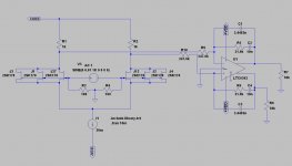
R9, R10 have to move to the OPA1632, parallel to the other RIAA components or we end up with huge noise and no gain.
I would BJT cascode the Interfets.
I think Zetex medium Power SMD is fine.
They ave low Rbb, high Hfe and can stand substantial idle.
Ok let me get these changes and re post
- Status
- This old topic is closed. If you want to reopen this topic, contact a moderator using the "Report Post" button.
- Home
- Source & Line
- Analogue Source
- Masterpiece