Well perhaps the fact that there are what appear to be a pair of Lundahl moving coil step up transformers directly under the white filament wiring might play a role in some of the noise pick up issues, the fact that the box is completely unshielded might also unfortunately play a role.
DC filaments will help here, rerouting the filament wiring would be even better, and applying copper foil inside the box and grounding it to the mecca ground will take care of electro-static pick up..
There is a reason why all of my phono stages are built on metal chassis and fully enclosed.
I don't use shielded wire in my phono stages because of the concern over capacitance at the input, and I have not had problems with noise pick up. The phono stage in question is extremely quiet.
Thanks for the replies.
The step up transformers aren't wired up yet (an MC cart is on the todo list).
Also, the heaters aren't floating, they are referenced in the PSU chassis (raised to about 60V above ground).
I've thought about re-routing the heaters, but that would add significant length, and in the case of the output caps (at the bottom), end up running parallel with them. I did take care to ensure the heaters crossed signal wires at 90 degress.
Also, in response to the ground loop, I am very famialir with that site (my headphone amp is a DoZ !), and the 0V line is connected to safety earth as it is in the article (without the diodes, just resistor and cap). I don't beleive it's a ground loop, as the buzz is quite harsh, and definitely not 50Hz.
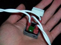
The black metal plate has a green wire to it. Does that mean it is connected to safety earth? Try to connect it to circuit gnd instead. That is one first step to a shielded box.
Maybe you can add some foil around the edges and on the bottom cover. With DC heating on top of that you have no source of hum in the box. Just the tubes sticking out.....
Maybe you can add some foil around the edges and on the bottom cover. With DC heating on top of that you have no source of hum in the box. Just the tubes sticking out.....
The black metal plate is connected to safety earth, which is then connected to circuit gnd (0V, the black wire) via a resistor and capacitor (not in the photo, I actually did it immediately after I took the shot !).
I don't have a bench supply, but I do have a 6V wallwart. It's only rated for 1.25A, but can try it for one section (or one channel)
I don't have a bench supply, but I do have a 6V wallwart. It's only rated for 1.25A, but can try it for one section (or one channel)
The black metal plate has a green wire to it. Does that mean it is connected to safety earth? Try to connect it to circuit gnd instead. That is one first step to a shielded box.
Maybe you can add some foil around the edges and on the bottom cover. With DC heating on top of that you have no source of hum in the box. Just the tubes sticking out.....
So I had a "quick" play this evening, and tried a few things.
First, was to remove the output tubes, and take the output of the input tubes direct to the output. This was whisper quiet, with only a tiny amount of hum (not buzz) on the output when I set my headphone amp to max.
Second, I removed the input tubes, and ran the grid of the input tubes to the grid of the output tubes. This was very noisy. I realise now (now that everything has been put away), that I should have short the grid of the output tube (as the way I had everything setup, any noise on the ccs of the first stage, would have been amplified in the second).
When I get my sanity back, I'll redo the test with the grid grounded, and determine whether the noise in in the second stage, of being amplified from the first.
I did also try using DC on the output tubes (input still had AC), but that was just as noisy (thinking about it now, noise of the first stage would still have been amplified into the second).
The buzz is definitely 100Hz though, so I guess that rules out heaters for the time being, and points to the PSU.
While your at it, see attachment--a ground loop breaker.
It may be useful to measure the voltage across the diodes prior to installing the resistor. If you've got any voltage readings (like 0.7v), there's a ground loop present.
See also schematic, but notice that the real bridge rectifier has a different pinout than the schematic shows. The real thing is shown in the attachment below:
Attachments
Last edited:
Does the diode actually make any difference in the loop breaker? I've gotten rid of ground loops before simply by adding the resistor and cap (which is what I have at the moment). I'll try this stuff over the weekend anyway. I think I need some sleep.
The difference is life or death. The resistor is not durable enough to blow a mains fuse or trip a mains breaker. Actually, the resistor itself is just barely counterproductive. It is the diodes (anti-parallel diodes, aka diode clipper) and cap that do the real work. You need the KBPC3510 shown if you want something strong enough to knock out a mains fuse when necessary to save your life or your house.
35a*1.43 = can deliver 50a for long enough to blow a mains fuse or trip a mains breaker. KBPC25**, 25a*1.43 = can deliver 36a long enough to trip a mains breaker.
If the 0.7v of one ground loop breaker is not enough room to roam, stack another series and get 1.4v (worth of potential shock). The diodes control how much shock you may get. So, use sturdy diodes.
Many electronics supply stores carry bridge rectifiers.
Say, with 0.7v span of the normal ground loop breaker, the resistor can be a 1/2w model. I've no idea why Rod Elliot's schematic has a 5w to cover a 0.7v span.
Its either ground loop breaker. . . or redo your turntable amp for differential/bridged/balanced output.
SO !
Bit of an update. Spent the afternoon poking and prodding, trying to find the source of the noise and buzz.
I added the diodes to the loop breaker circuit, and that seems to have cleared up the buzz (not going to say with 100% confidence, as I haven't hooked it up to my main system, just a smaller headphone amp that's easy to move around).
The noise was traced to the left channel, output tube (bottom left in the photo). I grounded the grids of both output tubes, and the noise was much higher in the left channel than right. I figured it may be the CCS, as the noise doesn't follow the tube. I then decided to remove the output tube, and just listen to the sound of the CCS. What I got was a very gently hum, no noise at all.
So, the noise is only there when the tube is plugged in. It doesn't follow the tube, and isn't the CCS, so all that's left is the socket, the cathode resistor, or the soldering (which has been reflowed).
Can a dodgy socket or cathode resistor lead to such noise ?
(and the DC going in is defintely noisy, so I'll definitely go ahead with a salas shunt reg)
Hi lordvader,
it is a challenge to discuss a noise problem that is actually happening on the other side of the world.
When you grounded the grids of the tubes you made sure you have no signal coming from the first stages and therefore ruled out a ground loop on the input. You could still have one on the output.
A ground loop always has to do with the following amplification. Your headphone amp might be different than the amp you used before. You may have an issue with one but not with other. This can be confusing. Do you have a line level audio transformer at hand that you could use to break to ground loop for a reliable test?
When you pulled the tubes to test the CCS behaviour. Was there a current path to ground for the CCS current to flow? If not, the CCS is likely to saturate and show no signal at all. The noise would be gone. The plate of a triode (or triode strapped pentode in your case) is not that low impedance. A misbehaving CCS could inject some noise there. But I have no real experience about htis. What I am trying to say is: the tube and the CCS can only produce noise as long as both of them are connected. A bad resistor or a bad connection in the socket will lead to cracking or static noise, but not to buzz or hum, in my experience.
With the tube pulled, the output of the CCS would have gone through a capacitor, then a 470K resistor to ground. Is that a sufficient path, or should the CCS been given a resistor directly ?
Also, thought tackling the buzz/hum is one of my problems, the noise issue is MUCH worse (like really bad radio static/white noise). The fact that it's localised to one area interesting.
In my haste to determine whether it was a dodgy resistor, I swapped cathode resistors of the two output tubes. Cleverly, I re-soldered one incorrectly, and managed to destroy the CCS (blown resistor, and after replacing the resistor, the noise coming out was a loud, squeaky static).
I'm going to have to get a new CCS. While I'm waiting, I think I'll replace the tube sockets. They're teflon loctal sockets (not yammamoto ones, $$$$$$$), but the solder tags seem really flimsy. I honstly wouldn't be suprised if there were some hairline cracks there (one did snap off during my initial build !). I've got ceramic sockets that seem MUCH more durable.
I added the diodes to the loop breaker circuit, and that seems to have cleared up the buzz (not going to say with 100% confidence, as I haven't hooked it up to my main system, just a smaller headphone amp that's easy to move around).
Don't be surprised if you need an additional ground loop breaker series to the first. Alternatively one can adjust the resistor to assure voltage drop, but if the voltage drop is beyond 0.7v then the diodes turn on and don't work any better than a solid wire. The resistor is a bit counterproductive anyway. What I'm trying to say that if 0.7v is not enough, then you might need more diodes (for 1.4v).
And, don't be surprised if your power amp needs a ground loop breaker circuit added.
And, if you've tried driving your grounded preamp from your grounded computer, you'll probably discover a need for a ground loop breaker in the preamp.
An alternative to this mess is differential/bridged/balanced audio that uses the ground for the shield but not for the signal.
Anyway, I'm glad to hear that you got the buzz portion of the noise solved.
P.S.
Next step seems to put schottky bridge rectifier, caps and low drop out regulator and ~100u for your heater circuit. You'll also want some ~330u at the amplifier end of that umbilical cable so it doesn't "look like" an inductive antenna. Much capacitance at the output of the regulator means you need to add the protective diodes to the regulator circuit, and the regulator datasheet probably mentions this. It is electronically better to put the regs in the amp enclosure; however, I was thinking heat dissipation could work better if the heater regs were in the power box.
P.P.S.
After that known 6.3v noise is gone, you can then add high voltage shunt reg to the turntable amplifier, and those HV regs should probably go in the turntable amplifier enclosure, located to do the most good.
You could use a resistor in the place of the ccs. If there is an instability caused by the Interaction of tube and ccs it will be gone with the resistor. I recently had trouble with an E88CC that was oscillating because I had made a mistake. What I heard was like you describe it. What does your scope show? Are there any grid stoppers in your circuit?
Ok. More updates
So I replaced the CCS of the output tubes with a 10K resistor. Everything measured fine (bias came to about 2V), so attached headphones.
Still horrible noise in one channel.
I replaced the socket (which is REALLY annoying !!!).
Still noise.
Bordering on losing my mind, I started jiggling things (power connectors, rca inputs and outputs). Then, when I bumped one of the RCA cabled, the noise went for a moment !
To cut an embarrasing story short, the source of the noise was a case of two rca connectors not making good contact with ground.
It was a bit of a coincidence though. The left channel RCA cable coming off my tonearm didn't make good contact with the input. Then, while I was testing, the left channel rca cable on the output didn't make good contact.
Der ...
There is still noise, but it's not as offensive (like gentle radio static), and equal in both channel. The 100Hz buzz is still there, but I'm putting that down to the noisy power supply (which is next on my list, once I get a fresh CCS, and build the SSHV2 regulator).
The gain of the phonostage is quite high, as is the gain on my headphone amp, so it doesn't take much to get into the noise zone (loadspeaker amp is low gain, so not as problematic).
There's still a bit of work to do, but I think I'm getting there
- Status
- This old topic is closed. If you want to reopen this topic, contact a moderator using the "Report Post" button.
- Home
- Source & Line
- Analogue Source
- Extremely noisy DC (Phono Stage PSU)