Hey all.
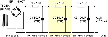
I'm currently trouble shooting noise problems on my tube phono stage (each channel contains two triode strapped C3gs, loaded by a CCS). The power supply is a schottky diode rectified with an RCRCRC filter (R = 270ohm, c = 50uF, except the last one, which is 100uF).
The power supply is in a seperate enclosure, and via the umbillical wire, I'm carrying B+, 0V, earth, and two 6.3VAC heater supplies (so 4 wires there). Each wire is tightly twisted with its opposing pole, and then covered in a shield (connected to earth).
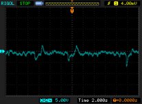
Anyway, when I connected the DC to a scope (the probe was on B+, the reference was the 0V line), the output looked like the attached file (this was taken from the phono chassis, not the PSU chassis).
Any clues ? If I zoom in, there is ripple, but it looks modulated on some really low frequency noise.
I'm currently trouble shooting noise problems on my tube phono stage (each channel contains two triode strapped C3gs, loaded by a CCS). The power supply is a schottky diode rectified with an RCRCRC filter (R = 270ohm, c = 50uF, except the last one, which is 100uF).
The power supply is in a seperate enclosure, and via the umbillical wire, I'm carrying B+, 0V, earth, and two 6.3VAC heater supplies (so 4 wires there). Each wire is tightly twisted with its opposing pole, and then covered in a shield (connected to earth).
Anyway, when I connected the DC to a scope (the probe was on B+, the reference was the 0V line), the output looked like the attached file (this was taken from the phono chassis, not the PSU chassis).
Any clues ? If I zoom in, there is ripple, but it looks modulated on some really low frequency noise.
Attachments
Hello,
is that 2s/DIV on your scope? That would mean you have a supply that varies rather than a noisy one.
Is the varaition larger close to the rectifier or close to the amplifier? Meaning: do we deal with a variation in mains or in load?
Your load should be a very constant one as it uses a CCS.
Have you compared the time constant of your filter chain to the "slew rate" of the voltage changes?
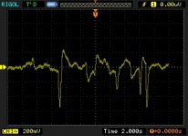
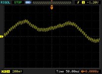
Well I took a trace of the PSU unloaded (close to the rectifier), and it looks the same (I also added a zoomed in trace, showing the actual ripple)
And yes, that's a 2s div.
My next question was going to be is if this is what motorboating looks like ?
And what do you mean by time constant of the chain, to slew rate of change ?
And yes, that's a 2s div.
My next question was going to be is if this is what motorboating looks like ?
And what do you mean by time constant of the chain, to slew rate of change ?
Attachments
The power supply is in a seperate enclosure, and via the umbillical wire, I'm carrying B+, 0V, earth, and two 6.3VAC heater supplies (so 4 wires there). Each wire is tightly twisted with its opposing pole, and then covered in a shield (connected to earth).
I notice two things.
Umbilical = big inductive resistor, so do you have at least 220u right next to the tubes (aka got caps in the amp enclosure)? I ask because, with inductance disabling the caps at HF, your amp has no defense against the unfiltered AC that is wrapped up with your DC power cable. Same flaw exists in most USB sound modules--dirty power in the same cable as signal line.
Perhaps, reg the heater supplies (clean DC heater?) within the power box and put some power caps in the amp box. Maybe that will get rid of the HF blast. I do not know.
I don't have any filter caps in the phono chassis, so that's something I'm planning on trying.
I'm also thinking about a filter cap next to each CCS (as there is a bit of distance between the B+ lug, and the CCSs).
The above images though (yellow traces) are of the PSU completely unloaded (well, only loaded by a 100K bleeder, and a 100K|33K voltage divider to raise the heaters).
I'm also thinking about a filter cap next to each CCS (as there is a bit of distance between the B+ lug, and the CCSs).
The above images though (yellow traces) are of the PSU completely unloaded (well, only loaded by a 100K bleeder, and a 100K|33K voltage divider to raise the heaters).
 Since this is trouble shooting a noisy phono stage it seems to me that this might better go in the analog source forum.. I'll retitle to reflect that it is a phono stage PSU..
I suspect the low frequency wander is probably slow cyclical variations in your mains voltage.. I see the same thing here...
You definitely need local decoupling at the CCS, perhaps even a few uF would be enough to assure that they are not misbehaving..
I use DC to heat the filaments in phono stages as this is just one less source of noise to couple into the audio circuitry, and more to the point variations in heater voltage will cause LF wander in the output of your phono stage.
Please post the design of both PSU and phono stage and we'll help you get it sorted. (See my Muscovite thread for the extremes I went to with the power supply - of course I used a cascode front end with zip for PSRR.)
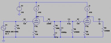
I'm attaching the PSU schematic, and phono schematic (note, that rather than 210 for B+, B+ it about 250V. The CCS drops the voltage to about 180V). The grid stoppers are also 1K rather than 120.
Also, the diodes are schottky diodes, so there are no snubbers on them.
The single B+ powers both channels, with each stage having its own star ground (ie, the first tubes share a star), and the stars then joining up to a single 0V point.
To decouple the CCS, would 10uF suffice ?
I'm thinking about DC for the filaments, but as they're already 6.3VAC, I don't think I can get 6.3VDC from them (well, get a nice 6.3VDC anyway).
Also, thanks for everyones input so far ! I'm been DIY'ing for a while, but this is my first "sensitive" project")
Also, the diodes are schottky diodes, so there are no snubbers on them.
The single B+ powers both channels, with each stage having its own star ground (ie, the first tubes share a star), and the stars then joining up to a single 0V point.
To decouple the CCS, would 10uF suffice ?
I'm thinking about DC for the filaments, but as they're already 6.3VAC, I don't think I can get 6.3VDC from them (well, get a nice 6.3VDC anyway).
Also, thanks for everyones input so far ! I'm been DIY'ing for a while, but this is my first "sensitive" project
Attachments
The inductance of the cable and the tracks does what any inductor will do and that's disable the remote caps from being useful at higher frequencies. The amount of patchwork needed relates to this, but I don't know the exact amount, since it is layout specific. However, the device is highly sensitive, so the most effective approach could be tuning it by ear (it is, after all, a device made to please an ear). That works as long as you pick the right spot to apply the fix. Perhaps someone smarter than me could name the correct value or plausible range of values for it?To decouple the CCS, would 10uF suffice?
Ordinary prefab bridge rectifier and caps will up the voltage to about 9.2vdc and then a regulator can work. You might need a schottky bridge rectifier (high amperage low voltage schottky specs are lowest loss) and a low dropout regulator though since I don't know how much rail droop is present.I'm thinking about DC for the filaments, but as they're already 6.3VAC, I don't think I can get 6.3VDC from them (well, get a nice 6.3VDC anyway).
You might have a look at the datasheet for onsemi NCP NCV (Low Dropout Linear Regulator) to see if they might meet your needs. When I searched for 1a or higher LDO's there weren't many to choose from.I'll have a go at DC rectifing when I get a chance, but there are about a million options out there when it comes to regulation !
I guess this: NCV317BT, NCV317BTG Low drop out version of LM317
The difference between a 6.3vdc regulated output versus 9.2vdc unregulated input is less than 3v (maybe less than the necessary margin of some normal regulators) and thus I think you might need an LDO (low drop out) regulator so that it won't mistakenly turn off during normal mains power fluctuations. I'm not good with maths, so please double-check.
Last edited:
Have a look at the LT1084 - 1086, the higher rated devices actually have slightly better drop out performance at moderate currents than the smaller ones do.
It would be preferable I think to find a transformer with 8V secondaries and rectify this with schottky diodes into an LT-1085 for example.
Even with the CCS I suspect the filtration in your supply is probably not sufficient, particularly as I have no clue as to what you are actually using. I would recommend investigating the Maida regulator that SY and others espouse as it will give you very stable and low noise DC - you really don't want a lot of variation here even with the CCS.
The Maida is a high voltage implementation of the LM317 with a high voltage transistor or fet that is configured to drop most of the voltage difference between the input and output of the supply - this so that the regulator never sees a voltage across it that exceeds its voltage rating.
I use the K And K CCS in my power amplifiers, and find they work quite well, but I have no idea of how high a PSRR they achieve in your circuit, even with 80dB or better (it's probably less) and a 1V low frequency variation on the raw supply this means something like 100uV could get through to be amplified by the following stage, where it might appear as several mV or more at the output of your phono stage.
The Salas HV shunt should be a very good solution to your issues - I've got one I'm going to use to power a future tube based I/V converter.
The Salas HV shunt should be a very good solution to your issues - I've got one I'm going to use to power a future tube based I/V converter.
Lordvader, it seems you have received a lot of good advice. The cure for your OP will probably be the HV regulator.
If you come back to the idea of a regulated DC heater supply, here are a few thoughts from when I did the same.
A rectified 6.3V will give 6.3*sqrt2 -2Uf. With a Shottky bridge that gives around 8.4V. Not to forget the ripple.
The LT LDOs are really nice. But I wanted to design something from components I had. I wanted a cheap and robust MOSFET as a pass element. It is hard to drive a Fet in the positive rail so I put in the gnd line. Used a reference, a PI and an error amp to drive it. The REF192 is probably a bit over the top, but that is what I had in the drawer. A TL431 would do nicely, I guess.
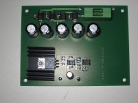
Here is the schematic and a photo of what it looks like on comfortably large pcb.
If you come back to the idea of a regulated DC heater supply, here are a few thoughts from when I did the same.
A rectified 6.3V will give 6.3*sqrt2 -2Uf. With a Shottky bridge that gives around 8.4V. Not to forget the ripple.
The LT LDOs are really nice. But I wanted to design something from components I had. I wanted a cheap and robust MOSFET as a pass element. It is hard to drive a Fet in the positive rail so I put in the gnd line. Used a reference, a PI and an error amp to drive it. The REF192 is probably a bit over the top, but that is what I had in the drawer. A TL431 would do nicely, I guess.
Here is the schematic and a photo of what it looks like on comfortably large pcb.
Attachments
Excellent idea, but a little bit of information is missing. Forward voltage drop pattern is a lot different between different models of Schottky and varies from 0.1v to about 3v. With the 6.3v heater circuit we don't want to drop voltage much. SO, for bridge rectifier, try the combination of "low voltage high current," such as MBR1035 or MBR1635, whereby the forward voltage drop chart looks much like a straight up wall and you won't get voltage loss.With a Shottky bridge that gives around 8.4V.
Hey all.
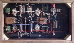
Though I'll upload a photo of the layout.
The only main difference is that the power to the top right CCS (red wire) goes over the heater wires (rather than under), and takes a more direct path (goes straight up, then left, rather than up, left, up).
The channel on the left (which happens to be the left channel), is particularly noisy, and there is buzzing in both channels (very noticable on my headphone amp, which has far too much gain). Originally I had a ground bus, which I replaced with the star arrangement you see here. Still there is buzz.
For the time being, I added a 220uF reservoir capacitor (near the bypass caps you can see on the right), and a 100uF decoupling cap near each CCS in the left channel (left the right channel alone for the time being, just wanted to hear what would happen). The reservoir cap, and decoupling has reduced noise a bit, but it's still there.
(haven't taken any measurements yet, will do that tomorrow).
Hopefully soon I can have a go with a HV regulator (if I rip out the bypass caps, I'll have heaps of space on the right side for a HV reg with heatsinks).
Attachments
Daniel, good point. The SS36 I used was in the drawer. It drops about 0.35V and you can certainly do better than that.
Unlike the heater circuit, the shottky with the biggest voltage drop curve, the Fairchild Stealth, when combined with a CRC can be used for that "open sound rectifier" in the high voltage tube amp power section. That idea is not the exclusive territory of tube rectifiers. But solid state is a bit more needy and you will want to use RC's across the transformer's primary and secondary windings.
If there's transformer amperage to spare, it seems that the use of some bleeder resistors could send some high voltage low current peaks to ground. A turntable amp is probably not loading the power supply much, so modest bleeder resistors could be worth a try for wasting some power noise peaks. But, I'm not guaranteeing any benefit from bleeder resistors--only saying worth a try. For favorable proportion, you can put soft switch diode series with bleeder resistors since noise will fire up a diode about a third harder than clean DC, thus you can trick the bleeder resistors into wasting more noise than clean power. Also worth a try, but not effectiveness not guaranteed.
Last edited:
Buzz?
Here's a briefing on the mostly likely cause of buzz: Ground Loop in your Hi-Fi? - Tricks and Techniques. . . I'm carrying B+, 0V, earth. . .and there is buzzing in both channels (very noticable on my headphone amp, which has far too much gain). Originally I had a ground bus, which I replaced with the star arrangement you see here. Still there is buzz.. . .
- Status
- This old topic is closed. If you want to reopen this topic, contact a moderator using the "Report Post" button.
- Home
- Source & Line
- Analogue Source
- Extremely noisy DC (Phono Stage PSU)