This amp stage consists of a differential cascode and instead the usual current source of the LTP there are two independend CCS. This means, one can adjust the open-loop gain by variation of the value from R6.
The question for me is which job does the jumper with ferrite beads like
http://www.wb5rvz.com/sdr/genesis_g40/images/06_ferrite_bead.gif
or
http://www.token.com.tw/inductor/image/inductor-filters-fb.jpg
(on Main PCB called "LK1" = link1), solder in parallel mode to R6 ??
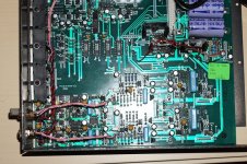
In the attached picture you will find the Tantal C2 between the phono input RCA sockets. "LK1" with ferrite beads and "R6" (3R3) you will find in the right of C2.
And some more questions:
Linn don't prefer a dc coupled mode. The choice of the capacitor in the signal pad (and NFB) are 100uF tantal in parallel mode with a 22uF tantal.
1) Are there a special benefit for this kind of parallel mode?
2) By which guidelines was fixed the polarity ??
3) How is to determine the voltage gain factor of this stage?
4) There are a ferrite bead on each base leg from Q3 and Q4 (2x CCS). Why?
P. S. Linn's LINTO (first series) uses the same circuit topology (some versions without the ferrite bead).
The question for me is which job does the jumper with ferrite beads like
http://www.wb5rvz.com/sdr/genesis_g40/images/06_ferrite_bead.gif
or
http://www.token.com.tw/inductor/image/inductor-filters-fb.jpg
(on Main PCB called "LK1" = link1), solder in parallel mode to R6 ??
In the attached picture you will find the Tantal C2 between the phono input RCA sockets. "LK1" with ferrite beads and "R6" (3R3) you will find in the right of C2.
And some more questions:
Linn don't prefer a dc coupled mode. The choice of the capacitor in the signal pad (and NFB) are 100uF tantal in parallel mode with a 22uF tantal.
1) Are there a special benefit for this kind of parallel mode?
2) By which guidelines was fixed the polarity ??
3) How is to determine the voltage gain factor of this stage?
4) There are a ferrite bead on each base leg from Q3 and Q4 (2x CCS). Why?
P. S. Linn's LINTO (first series) uses the same circuit topology (some versions without the ferrite bead).
Attachments
Last edited:
4) There are a ferrite bead on each base leg from Q3 and Q4 (2x CCS). Why?
P. S. Linn's LINTO (first series) uses the same circuit topology (some versions without the ferrite bead).
No expert but ferrite beads are used to filter HF/RF out. Maybe to avoid oscillation ?
The beads (usually very lossy) are used both the prevent oscillation and to reduce susceptibility to external EMI.
Paralleling different values of electrolytics is usually done to reduce the effects of parasitics in the capacitors in very low level, low impedance circuits. (or in power supply decoupling to assure low decoupling impedances over wide frequency ranges - the danger in doing this is ESL in the large capacitor my resonate with the smaller capacitors, there are techniques to deal with this) I use this technique with very large electrolytics.
Tantalums are a pretty lousy choice for audio coupling caps due to some inherent distortion generating mechanisms particularly with small values of DC across the cap. Oscons or low impedance AL electrolytics may be a better choice if chosen appropriately.
The beads (usually very lossy) are used both the prevent oscillation and to reduce susceptibility to external EMI.
Same meaning, different words
")
BTW modern tantalum caps perform much better than described....
- Status
- This old topic is closed. If you want to reopen this topic, contact a moderator using the "Report Post" button.
- Home
- Source & Line
- Analogue Source
- Strange Features by the MC Head Amp Circuit of Linn's LK-1 (LK1)