.I remember that from Wireless World in the late 70's or early 80'sIt was a John Lindsey Hood article. Still got it somewhere
Wireless World 1983, January, vol. 89,
1561(4), p. 46-49
Linsley Hood
.
1561 or 1564
.
It depends on the circuit, which would need to include a suitable coupling capacitor to implement the LF rolloff. Not all RIAA circuits include this. The added resistor raises the rolloff frequency for anti-phase (i.e. vertical) signal only.Skorpio said:Hi,
Could you tell where this would be?
O a whim I entered "derumbleizer" as a search term to see what came up. I invented the thing and if anyone wants an explanation of how it works, you can email me at the address on the website for the device, (mention the thread) or respond here. Some years ago I saw a bass summing preamp in an old issue of Popular Electronics. I simulated the PE circuit and found a hump in the frequency response. I then decided to figure out a different and better way to do it. Some months later I succeeded and implemented the circuit in a preamp I use every day to do record restorations. It has separate variable bass, midrange and treble equalization settings in order to be able to properly play 78rpm records. I took it to a local audiophile club so they could audition it and I could get feedback. They said it sounded like it cost twice the price! High praise since some of the gear they were playing with that week cost more than both our cars combined.
I have a tube RIAA pre-amp connected to a PP 30+30 Watts, all self build, recently noted this rumbling movement on my Fostex FE206en while playing a vinyl, tested with a spectrum analyzer I spot huge pick on the range of 6/8 Hz, I have an unused EQ Behringer FBQ3102HD, so I try to insert it on the line between the RIAA and the amp and after some setting of the low cut knob problem solved, I cannot ear any difference on the sound quality so problem solved, I am not digitalizing or restoring old record just listening good music, I found anyway this thread very interesting,,,,all the best to all ..


Douglas Self's circuit has an all-pass response for signals where left and right are equal ("in-phase signals"), so you get some phase aberrations. After reading his article "The Devinyliser", Linear Audio vol. 11 , I made an attempt to come up with something that filters the antiphase signals steeply with a well-behaved high-pass response and has a unity transfer for in-phase signals, rather than an all-pass transfer. I succeeded, but my circuit had its own and probably worse disadvantages: the channel separation only increased with a first-order slope above the cut-off frequency, there was a deep dip in the left-to-left and right-to-right responses around the cut-off frequency and a slight bump in the left-to-right and right-to-left responses around the same frequency.
In the end I could come up with a compromise circuit where the transfer for in-phase signals is still unity, the response for anti-phase signals rolls off slightly steeper than first order below the cut-off frequency and the channel separation increases slightly faster than first order above the cut-off frequency, while keeping any bumps and dips down to a reasonable level.
See Linear Audio volume 12 for all the details or the attachments for just my circuits. Figure 4 is a version with fourth-order Butterworth high-pass response for out-of-phase signals, a major dip in the left-to-left and right-to-right responses and only slowly increasing channel separation. Figure 11 is the compromise circuit. Figure 10 shows its responses: the out-of-phase response is 1 – Hfilter, the left-to-left transfer is 1 – Hfilter/2 and the left-to-right transfer is Hfilter/2, all are expressed in dB with the frequency axis normalized to the cut-off frequency. Figures 4 and 11 are just LTSpice circuits; to turn them into something you can actually build, just replace the unity gain voltage-controlled voltage sources with op-amps connected as voltage followers and the high-gain voltage-controlled voltage sources with op-amps.
Attachments
Last edited:
Hi Marcel
I was a subscriber to Linear Audio, and until I read it again I must admit that I'd forgotten your very detailed letter response to the devinyliser article. The whole topic of cross-feed rumble (actually warp) filters is very interesting. I remember long ago, when vinyl records were the only show in town, reading around this topic in articles in Wireless World.
They are all compromises and performance trade-offs one way or another.
Since I use open baffle speakers (Linwitz LX521), some form of taming of warp and ripples in the vinyl is kind of essential. I actually use the Self circuit, which I can bypass when listening to digital media. Although that is not immune to low frequency non-music related signals at a few Hz, which I suspect is a studio air conditioning anomaly.
Craig
I think Douglas Self's compromise, accepting the poor phase response of an all-pass transfer for in-phase (L = R) signals, is a very sensible one, inelegant as it may seem. You might be able to get rid of all the issues I mentioned with a phase-linear digital implementation, but then you get pre-echoes in return - and to me it would spoil the fun of listening to an analogue source.
Douglas Self's circuit has an all-pass response for signals where left and right are equal ("in-phase signals"), so you get some phase aberrations. After reading his article "The Devinyliser", Linear Audio vol. 11 , I made an attempt to come up with something that filters the antiphase signals steeply with a well-behaved high-pass response and has a unity transfer for in-phase signals, rather than an all-pass transfer. I succeeded, but my circuit had its own and probably worse disadvantages: the channel separation only increased with a first-order slope above the cut-off frequency, there was a deep dip in the left-to-left and right-to-right responses around the cut-off frequency and a slight bump in the left-to-right and right-to-left responses around the same frequency.
In the end I could come up with a compromise circuit where the transfer for in-phase signals is still unity, the response for anti-phase signals rolls off slightly steeper than first order below the cut-off frequency and the channel separation increases slightly faster than first order above the cut-off frequency, while keeping any bumps and dips down to a reasonable level.
See Linear Audio volume 12 for all the details or the attachments for just my circuits. Figure 4 is a version with fourth-order Butterworth high-pass response for out-of-phase signals, a major dip in the left-to-left and right-to-right responses and only slowly increasing channel separation. Figure 11 is the compromise circuit. Figure 10 shows its responses: the out-of-phase response is 1 – Hfilter, the left-to-left transfer is 1 – Hfilter/2 and the left-to-right transfer is Hfilter/2, all are expressed in dB with the frequency axis normalized to the cut-off frequency. Figures 4 and 11 are just LTSpice circuits; to turn them into something you can actually build, just replace the unity gain voltage-controlled voltage sources with op-amps connected as voltage followers and the high-gain voltage-controlled voltage sources with op-amps.
Very interesting thanks, just one question, do you have a specific op-amps in mind that can be used on the Figure 11 ? I try on Ltspice different op-amps and the response change a bit......all the best
That's funny... I would expect it to work well with just about any unity-gain-stable voltage-feedback op-amp with a gain-bandwidth product of a few megahertz or more. For example the TL071...TL074 series, OPA134...OPA4134, NE5532 or the NE5534 with a 22 pF external compensation capacitor. I would not recommend the LM358 or the LM324, though, because of their class-C output stages and small gain-bandwidth product.
What op-amps did you try?
What op-amps did you try?
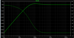
I'd say the 1178 is not really good for the application. It is a micropower opamp with a somewhat pathetic slew rate of 0.025V/us. It is little wonder that it has problems in the higher audio frequencies.
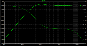
The 1115 is *much* better, with a 10V/us slew rate, and decent specs across the board. They are really expensive though. Personally I'd just take Marcel's advice - in particular the 5532 is a solid workhorse and costs less than a tenth that of the 1115.
The 1115 is *much* better, with a 10V/us slew rate, and decent specs across the board. They are really expensive though. Personally I'd just take Marcel's advice - in particular the 5532 is a solid workhorse and costs less than a tenth that of the 1115.
Last edited:
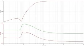
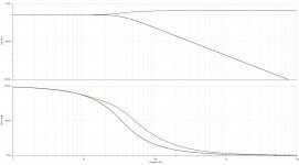
I try with LT1178 and the response in the first picture on the left then LT1115 second picture.......thanks again
Plot group delay on the right hand axis.
Im afraid with standard filter approaches, phase shift comes with the territory- but in my experience for rumble, it makes little difference. (I can switch mine in and out - Sallen-Key type).
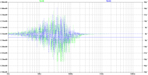
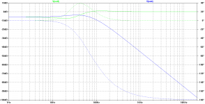
It's a crossfeed system with unity in-phase response, so by design, the phase response for L = R looks much better than the phase response for L = -R, see the attachments. The plots are for left and right in phase with unity amplitude, left and right 180 degrees out of phase with unity amplitude, and for unity amplitude left and silence right. The idea behind these crossfeed systems is that low-frequency audio is usually panned to the centre, so L = R, while rumble and record warps are predominantly out of phase, so L = -R.
Attachments
Last edited:
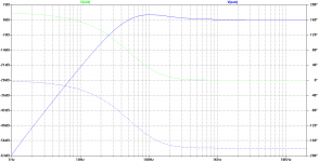
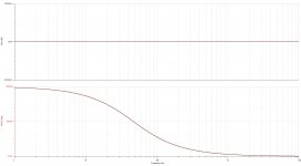
This is Self's circuit on the same scales as Marcel's, other than I've re-scaled the vertical axis on the first one. The effect of the all pass is seen in the antiphase signals - but that only relates to antiphase warp and vinyl ripple signals that are way down in amplitude. The in phase and one signal silent music signals are much more polite phase responses, although the in-phase is not the flat line of Marcels.
Attachments
Last edited:
- Status
- This old topic is closed. If you want to reopen this topic, contact a moderator using the "Report Post" button.
- Home
- Source & Line
- Analogue Source
- The ultimate rumble filter - far more effective than just a high pass filter!