Thank you Frans. I'll post tomorrow a couple of pics of the PCB's.
I've already read the threads about PSU, but being not a specialist, with little understanding about electronics, you know... Explain me a thing. I bought two transformers rated 2X24 V at 750 mA (Triad). But I measured 2X28 V AC. Is this OK? That gives at the end of the pre-reg +/- 39 V DC without any load.
Emil
That's o.k. when not loaded the voltage may be a bit higher then nominal. The DC voltage is, about, 1.4 times the AC voltage. (and 1.4 * 28 = 39.2).
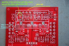
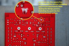
I think the issue of the shortage to ground is only on the latest batch of PCB's. My guess is that in order to make room for the compensation capacitors in the shunt, the resistor was moved to the right. In the same time the clearance rectangle from the bottom layer was not moved to the right, so the rightmost end of the resistor now accidentally connects the ground plane on the bottom layer. Maybe Alfred can confirm that also on the PCB file?
That connection should be removed, otherwise the short circuit can also create issues for the previous box (the pre-regulator).
That connection should be removed, otherwise the short circuit can also create issues for the previous box (the pre-regulator).
What do you think Alfred?
Emil
hi guys, so sorry about this mistake!! my sincere apologies....
the layout is quite crowded and double-sided, should have done a better job in checking the result and run one more DRC and ERC....
thanks a lot emil for the fix, i will also email this to all subscribers
alfred
hi guys, so sorry about this mistake!! my sincere apologies....
the layout is quite crowded and double-sided, should have done a better job in checking the result and run one more DRC and ERC....
thanks a lot emil for the fix, i will also email this to all subscribers
alfred
My boards do not have this issue....
hi guys, so sorry about this mistake!! my sincere apologies....
the layout is quite crowded and double-sided, should have done a better job in checking the result and run one more DRC and ERC....
thanks a lot emil for the fix, i will also email this to all subscribers
alfred
Hi Alfred,
FYI.
This morning I checked (with a magnifier) my pcb "R2 edition 2012":
Every solder point (I did upper & under side) is (méga-)cool OK .... no problem with the layout ...
Congrats (for R2/2012).
It's music ... I like it.
Allez, salukes.
Karel
It is indeed a minor issue, and easy to be sorted. It is still the best PCB I have worked until now, concerning the quality of the traces and soldering pads. It is important to have this corrected, but it was not intended as a critique, Alfred, as without your hard and free work, we would not have this beauty to work with.
Cheers!
Cheers!
"hobbyists" is close enough for full meaning in English.")
Where is the moderator when you need him?

You stupid DIY'er http://www.youtube.com/watch?v=kFZTko2TXNY&feature=player_detailpage#t=5s
Last edited:
Allez, Sullekes
What I standard do nowadays is make pictures of boards with a digital camera, before and after the populating.
(as cigarette lighters and cell phones, I regard camera's as disposable items, use only the shittiest)
During the pad & trace looking on the LCD monitor, a print-out of the images serves as a checklist.
Each of the boards I received from the R1 batch is faultless (4 PCB's for balanced)
I have a question regarding hum - I had a rather large case available which I wanted to use for the Paradise. I know its not the prefered solution but since its a bit large I wanted to put in amps and PS. Amp boards stacked on one side devided by 1.5mm steel and the PS modules with transformers on the other. In the middle I intented to have two more steel sheets to accomodate the rotary switch between them and provide some shielding between PS and amp.
Anyway, as expected - hum. Before I disassemble it and go for a two box solution I wanted to ask whether somebody has an additional idea I could try.
Currently the metal case is connected to safty earth. As are the transformer cores and the rest of the metal including the sheet between the amps.
The 2 amp grounds are connected to the metal case via 2 DDRC elements. Turntable earth is connected to one of the amp grounds.
When I start to play around and connect/disconnect/reconnect elsewhere neither the TT earth nor the safty earth change anything. Only thing that helps is if I put the metal sheets in the middle (not shown). Then the hum gets smaller.
I conclude this is not a ground loop problem but the stray field of the transformers is too large and I won't have a choice but move them away. Any different views?
Many Thanks
Sven
An externally hosted image should be here but it was not working when we last tested it.
Anyway, as expected - hum. Before I disassemble it and go for a two box solution I wanted to ask whether somebody has an additional idea I could try.
Currently the metal case is connected to safty earth. As are the transformer cores and the rest of the metal including the sheet between the amps.
The 2 amp grounds are connected to the metal case via 2 DDRC elements. Turntable earth is connected to one of the amp grounds.
When I start to play around and connect/disconnect/reconnect elsewhere neither the TT earth nor the safty earth change anything. Only thing that helps is if I put the metal sheets in the middle (not shown). Then the hum gets smaller.
I conclude this is not a ground loop problem but the stray field of the transformers is too large and I won't have a choice but move them away. Any different views?
Many Thanks
Sven
- Home
- Source & Line
- Analogue Source
- Paradise Builders