Supposedly this is the proper thread to ask these questions:
1. What is the size of the boards (I browsed all the threads looking for this info but for some reasons I failed to get it)?
2. On the first post in the group buy thread for the parts, there is the official BOM, in which I can find the description "Panasonic SMD electrolytic cap, d=16 RM=7.5" for the 4700uF/16V value caps and also for the 6800uF/6.3V. Anyway, in all the builds pictures around there are apparently only Through-Hole Components for these positions, not SMDs. Is it any other BOM more updated, or the new boards have to be stuffed with SMDs?
I may have overlooked some info (my apologies in that case - although it took me loads of time to read all this and related threads) but waiting for the boards to be ready I would like to plan the case and gather all the parts. Or maybe there is a wiki page that I missed?
Thanks for your help!
Alfred, when you implement the Calvin buffer please tell me how you like it.
I get really good results, especially more transparency and slam.
Hi Joachim and all,
just put the buffer in and did some hearing. I must say it is very nice! Comparing to the regular Paradise output buffer, the bass is very well structured, there is more texture there, and the transparency is amazing. I had a feeling that everything is slightly more forward, more "visible", and the spatial resolution as well as the timing is a nice improvement. The highs are more there, more in your face, but not aggressively so. It is just clearer. The best part I think are the microdetails, lots of them and just right.
The regular buffer is not bad, dont get me wrong, but the calvin buffer makes it much more believable and clearer. Maybe it was the longish cables and low input impedance of my line stage, that the regular buffer just couldnt cope with so well....
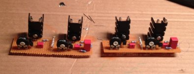
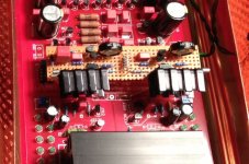
Please see the pictures on how I implemented. I just did little PCBs as "backpacks" to the regular PCB, where I removed Q99 and Q91 (so the way back is not too painful
 )
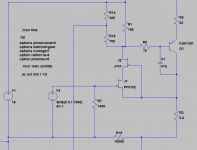
)I also changed a few components, see schematic. Here I used the PF5102 cascoded with J109, and the 2SA1381 as output PNP. The simulation showed -3dB at 32MHz or so, and 0.000006% THD - whatever.... it sounds mighty fine....
Thinking now about making a new line stage, using a 1:1 transformer and two buffers for symmetric output....
Attachments
Last edited:
Hi Joachim and all,
just put the buffer in and did some hearing. I must say it is very nice! Comparing to the regular Paradise output buffer, the bass is very well structured, there is more texture there, and the transparency is amazing. I had a feeling that everything is slightly more forward, more "visible", and the spatial resolution as well as the timing is a nice improvement. The highs are more there, more in your face, but not aggressively so. It is just clearer. The best part I think are the microdetails, lots of them and just right.
The regular buffer is not bad, dont get me wrong, but the calvin buffer makes it much more believable and clearer. Maybe it was the longish cables and low input impedance of my line stage, that the regular buffer just couldnt cope with so well....
Please see the pictures on how I implemented. I just did little PCBs as "backpacks" to the regular PCB, where I removed Q99 and Q91 (so the way back is not too painful
I also changed a few components, see schematic. Here I used the PF5102 cascoded with J109, and the 2SA1381 as output PNP. The simulation showed -3dB at 32MHz or so, and 0.000006% THD - whatever.... it sounds mighty fine....
Thinking now about making a new line stage, using a 1:1 transformer and two buffers for symmetric output....
Looks very good
Here is the full schematic of my implementation. Please note I have replaced R14/R16 and R17/R19 with a 1kOhm trimpot each, but I just set them to the value the simulation indicated. In the Paradise, the buffer is inside the servo loop, so adjusting the offset would have to be done outside. The output zobel is not shown here but implemented just as in Calvin's schematic.
I will look into a little PCB for this....
I will look into a little PCB for this....
Attachments
Sorry I left those in. Yes, R7 is just an input resistor and has no function in the circuit. Its parallel to a voltage source so it does not affect simulation. R15 is the output resistor I used in the simulation, just to have some load on the output. The output is just below R3.

still the Wima caps, unfortunately. Still, it sounds very nice. Vcaps will be the next upgrade, they are sitting there and waiting for me to find the time. Plus, a few more modifications- some exotic input trannies, a new servo, cooling for the input stage, .......
on my way to the Paradise Platinum Extreme......
on my way to the Paradise Platinum Extreme......
- Home
- Source & Line
- Analogue Source
- Paradise Builders