Long time ago here a couple of preliminary drawing (I am sure you can do better than me)
One is Split passive and did run for couple of yearstry ed AD797 but was a bit to metallic
second was going to be, till I got infected by MPP and decided to try and learn sumthink about transistors, tanks so much, to late now to realize that Public forum is not right place.
LT1028 is BJT low noise voltage wise Current wise noise is sort of forget to mention it so data sheet looks better .
But said before Frans got better...
Cant promise much all old file are in secret puter never connected to intra web at present in the loft untouched for quite a while
Remove C6 or U6 (I would go for C6 and make it DC). Also, I do not like the instrumentation amp (to much silicon and only needed if a high input impedance is needed).
Why the question mark, and where are the listening reports?
http://www.diyaudio.com/forums/analogue-source/165603-balanced-input-all-dc-coupled-riaa-preamp.html
Re reading
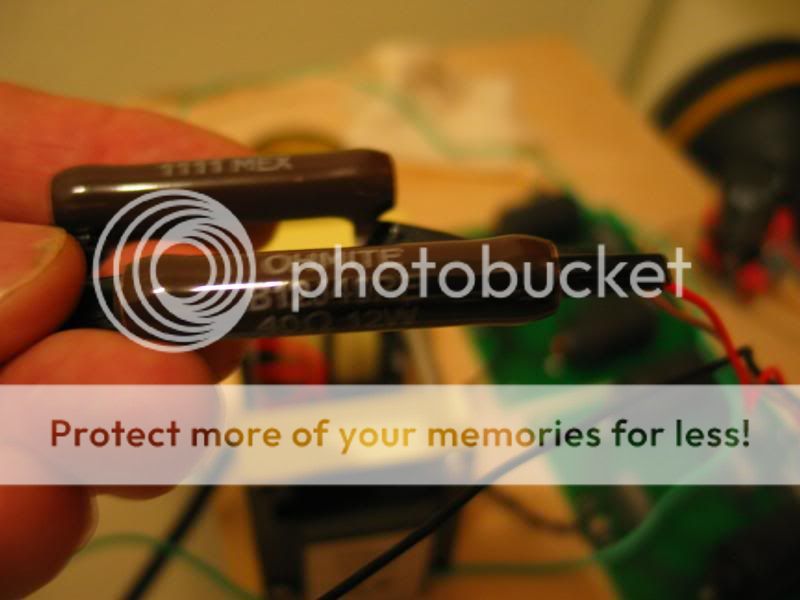
I got some 40ohm 12 watt wirewound ceramic resistors to lower voltage.
The 40R resistor lowered the voltage from 36v to 26v, so i am right where i need to be. But i can only touch them for a split second cause they are hot.
Are these made to handle this wattage and heat??
Also I have a 330r resistor on the input with a 30ohm cart, started with a 100r resistor but it seemed a tad bright and noisy as it was a cheap resistor.
Right now it seems a bit bass heavy, would i lower the input to 220r??
Not sure if going higher value on the input increases bass or lowers it.
Thanks...
Are these made to handle this wattage and heat??
They can, if they can get rid of the heat.
If you're holding them in your hand, they can't.
You need to mount the Brown Devils, the mounting bolt removes the heat. (you know, the willie goes in the hole)
Without, they go hot, and do not make the 12 watt stretch.
(12W if at 77F, 8W at ~270F, 4W at ~465F, Zero watts at 660F)
If you got enough to spare.
Extra RC
2 X 40 Hom's in parallel capacitor 2 X 40 Hom's in parallel
still get the magic 26 V and get rid of same ripple.
20 Hom's 24 W should give you 1/4 of the heat.
Cheaper than proper new trafos with correct voltages and you could fit the last RC near the Phono Stages.
Extra RC
2 X 40 Hom's in parallel capacitor 2 X 40 Hom's in parallel
still get the magic 26 V and get rid of same ripple.
20 Hom's 24 W should give you 1/4 of the heat.
Cheaper than proper new trafos with correct voltages and you could fit the last RC near the Phono Stages.
Attachments
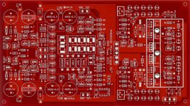
Hi guys. Just getting started with my build. Sorted the transistors and started soldering. This is my first pcb build, have built everything in my rig point to point and tube. I have a really nice tube phono stage now and use peerles/altec 4722 suts. Am putting a second tt into the mix and was going to build another tube phono but thought, hey, try something new and so here I am. I have baseline barely worthy of your attention queries. I am good with copying builds from pictures. Following pcb traces and determining the relationship to the schematic is not really a strength of mine. In the build guide there are circled groupings of the transistors to keep matched as a grouping from the schematic. Any chance I could see these groups transposed to the pcb image? I feel like I am getting good solder joints so the first hurdle is crossed, as well as getting the leds properly indexed... Thanks in advance for your time and attention. Is there also any chance that someone from the group buy has a nice finished pick to assist me in loading the board?
Kind regards, Bill
Kind regards, Bill
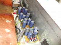
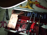
Here is what I have at present
RCruz did same real nice ones with numbered components wish I could find them...
Those are R2 boards and have very small differences from R3 (off set pot and couple of foot prints)
Transistors grouping is quite evident from lay out and is also on Guide
RCruz did same real nice ones with numbered components wish I could find them...
Those are R2 boards and have very small differences from R3 (off set pot and couple of foot prints)
Transistors grouping is quite evident from lay out and is also on Guide
Attachments
Why the question mark, and where are the listening reports?
http://www.diyaudio.com/forums/analogue-source/165603-balanced-input-all-dc-coupled-riaa-preamp.html
Sorry if I did not pick up this earlier to many relief I got quite busy finding new place for FiFI.(moving home by end of next month)
Question mark is there because me dumb and can not post correct tread name.
The fact that is worth looking at it is not disputed and I agree INA like may be to much silicon.
Listening reports (and real shame on me) I have not done as I want to have back to back compare with the INA like stage.
Paring Oranges and Apples is big mucho mistake as intended constructive criticism may not be taken as constructive (I know Frans got thicker skin than same but one (me) eventually learn from mistakes)
I got a few months ahead of me brandishing big hammer and not going back to the excellent http://www.diyaudio.com/forums/analogue-source/165603-balanced-input-all-dc-coupled-riaa-preamp.html is one of the many things bugging me every day
Besides ears still ringin from last one I did.
Here is what I have at present
RCruz did same real nice ones with numbered components wish I could find them...
Those are R2 boards and have very small differences from R3 (off set pot and couple of foot prints)
Transistors grouping is quite evident from lay out and is also on Guide
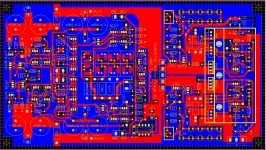
Here it is.
Each transistor has the same number as in the schematic.
Attachments
Sorry if I did not pick up this earlier to many relief I got quite busy finding new place for FiFI.(moving home by end of next month)
Question mark is there because me dumb and can not post correct tread name.
The fact that is worth looking at it is not disputed and I agree INA like may be to much silicon.
Listening reports (and real shame on me) I have not done as I want to have back to back compare with the INA like stage.
Paring Oranges and Apples is big mucho mistake as intended constructive criticism may not be taken as constructive (I know Frans got thicker skin than same but one (me) eventually learn from mistakes)
I got a few months ahead of me brandishing big hammer and not going back to the excellent http://www.diyaudio.com/forums/analogue-source/165603-balanced-input-all-dc-coupled-riaa-preamp.html is one of the many things bugging me every day
Besides ears still ringin from last one I did.
So? soon then?
Just letting you know that I really would like to see those comparison reports, but I am not in a hurry, just curious.Here it is.
Each transistor has the same number as in the schematic.
Many thanks Ricardo, this must have been a lot of work!
 Cheers
I am trying to move forward without a pc. It went up in smoke a few weeks ago and I have been trying to get by on my phone for now. Needed the extra $$$for the ps group buy! First things first. So, I printed out the build guide at a friend's but it doesn't have sufficient resolution on the picture with the circled transistor groupings to discern what is what.
The side of the board with the leds and heatsinks is the output side? The group of eight input transistors is on the side opposite the leds in the center? This is where I need the high value transistors? Eight similar pieces of each from my batch of transistors will be in the 440range.
The side of the board with the leds and heatsinks is the output side? The group of eight input transistors is on the side opposite the leds in the center? This is where I need the high value transistors? Eight similar pieces of each from my batch of transistors will be in the 440range.
- Home
- Source & Line
- Analogue Source
- Paradise Builders