No, I do notbut in this (and exactly this) situations, it may be that a higher Cob is more preventative towards oscillation, and then again, it may be the other way around. That is why I am happy to someone using high Ft low Cob transistors in the PSU (as I told Salas (at the least tried to tell (o.k. now I am over-explaining things (I got to stop (now
P.s. Please make next a long question, for a short and easy answer
Way cool answer..... I like it
P.S. You guys did you specify the local terminating 10uF lytics ESR by any chance? That can be a variant between types to give instability if its not indifferent by design.
Maybe a small resistor in series.... EL Zobel
This was a mistake, next time I would specify a (greater than) 500mOhm ESR or series resistance (this is more specific
Yes, that is what I was saying, the 500mOhms external (from the capacitor) resistor (having it's own set of holes in the PCB)
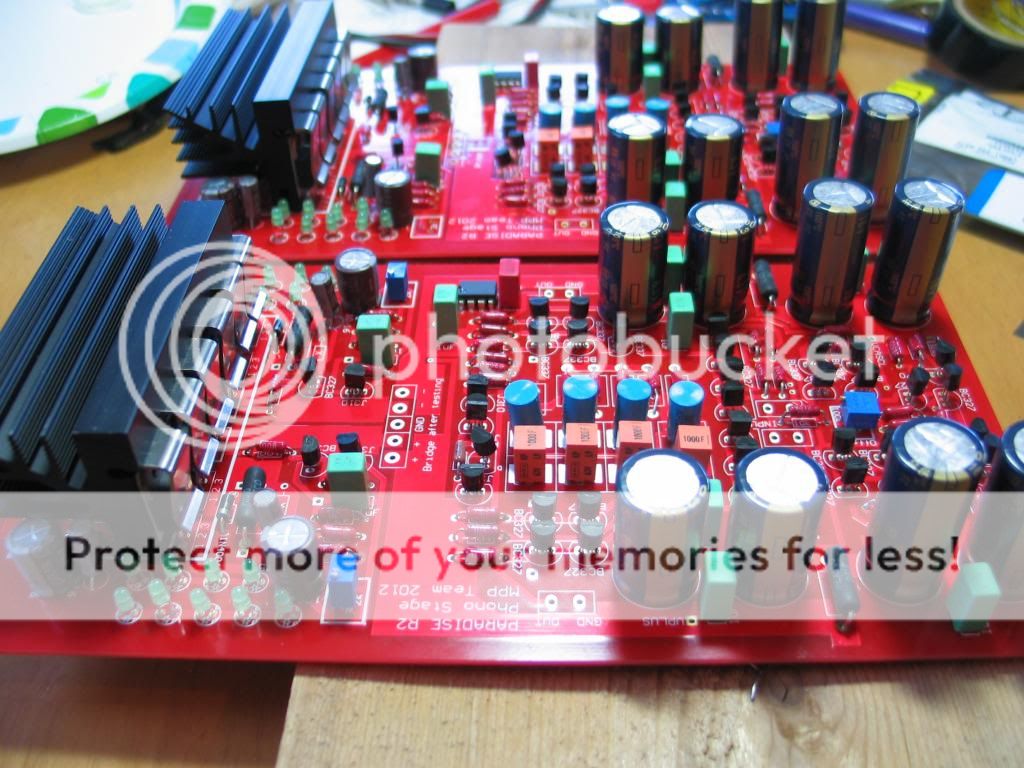
Sorry these aren't lite up, i dont have a lab supply or test equipment. They are being shipped off to a buddy to lend a hand, unless someone in Austin Tx can help me out.
Cant wait to hear these, thanks to all.......
Looks nice and clean, we will see what happens next (good chance it just works).
PSU test
Made a PSU unit with 2SA1930/2SC5171 TOSHIBA VAS grade BJTs. PMOS IRF9610 NMOS IRF610. 10uF caps = Nippon KMQ 100V 105C. 100uF caps = Nippon KY 25V 105C. Vin-Vout for reaching 140mA CCS (load demand will be 70mA per rail) = 7V. Rise above ambient on sink behind the power semis = 26C (48C with 22C room temp). Drift = -90mV over settling time = 20 minutes. No parasitic oscillations whatsoever. I.e. this PSU build is stable on its own before connected to its target load.
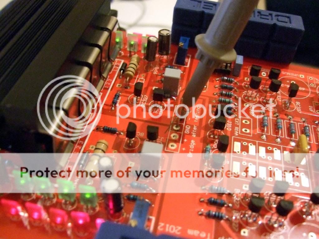
Notes: 1. Preparing and aligning the sink is a royal PITA. 2. Its sinking capacity is borderline. I would stay +6V to +7V Vin at most. I.e. 2X18VAC should do.
3. Is there statistical info about using the several 1uF film caps on the phono rails or not when oscillations happened?
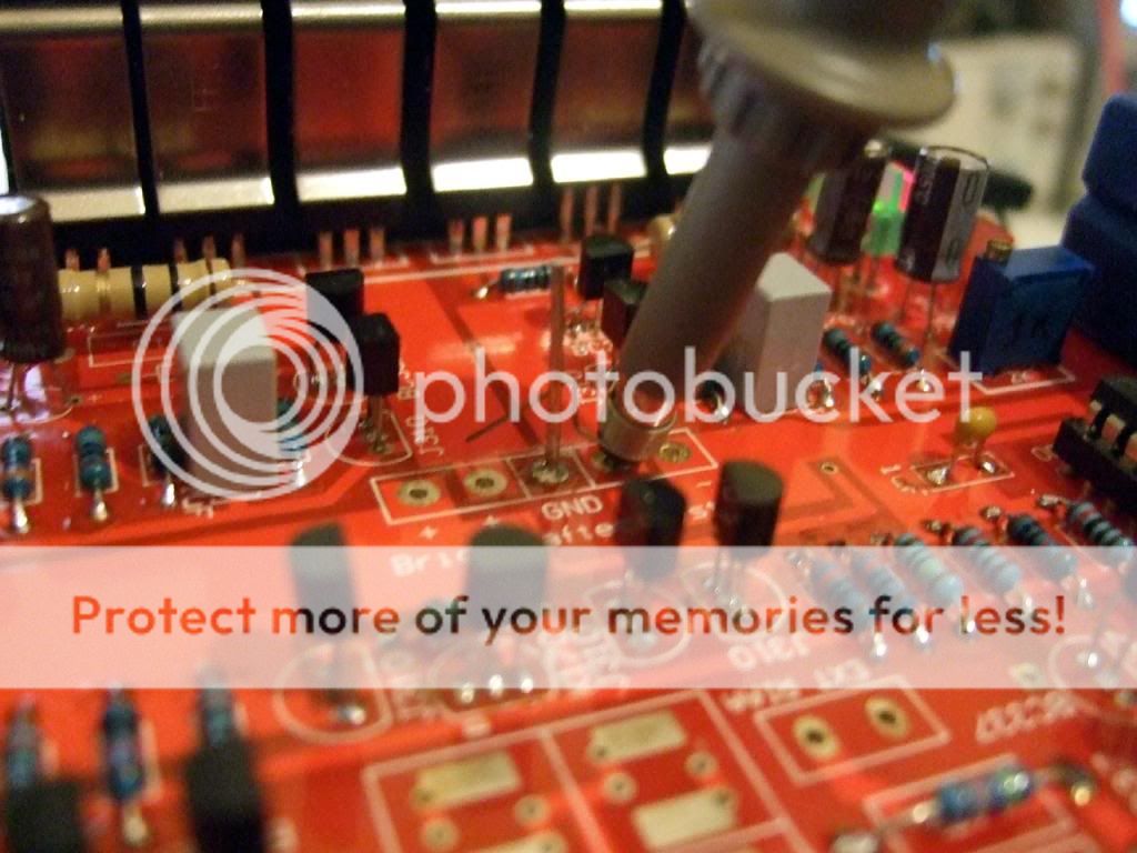
4. Use short path to ground when probing for oscillations.
Made a PSU unit with 2SA1930/2SC5171 TOSHIBA VAS grade BJTs. PMOS IRF9610 NMOS IRF610. 10uF caps = Nippon KMQ 100V 105C. 100uF caps = Nippon KY 25V 105C. Vin-Vout for reaching 140mA CCS (load demand will be 70mA per rail) = 7V. Rise above ambient on sink behind the power semis = 26C (48C with 22C room temp). Drift = -90mV over settling time = 20 minutes. No parasitic oscillations whatsoever. I.e. this PSU build is stable on its own before connected to its target load.
Notes: 1. Preparing and aligning the sink is a royal PITA.
2. Its sinking capacity is borderline. I would stay +6V to +7V Vin at most. I.e. 2X18VAC should do.3. Is there statistical info about using the several 1uF film caps on the phono rails or not when oscillations happened?
4. Use short path to ground when probing for oscillations.
Sorry these aren't lite up, i dont have a lab supply or test equipment. They are being shipped off to a buddy to lend a hand, unless someone in Austin Tx can help me out.
Cant wait to hear these, thanks to all.......
Very nice! Just out of curiosity, what are the blue caps you use in the RIAA section?
Made a PSU unit with 2SA1930/2SC5171 TOSHIBA VAS grade BJTs. PMOS IRF9610 NMOS IRF610. 10uF caps = Nippon KMQ 100V 105C. 100uF caps = Nippon KY 25V 105C. Vin-Vout for reaching 140mA CCS (load demand will be 70mA per rail) = 7V. Rise above ambient on sink behind the power semis = 26C (48C with 22C room temp). Drift = -90mV over settling time = 20 minutes. No parasitic oscillations whatsoever. I.e. this PSU build is stable on its own before connected to its target load.
Notes:
1. Preparing and aligning the sink is a royal PITA.
2. Its sinking capacity is borderline. I would stay +6V to +7V Vin at most. I.e. 2X18VAC should do.
3. Is there statistical info about using the several 1uF film caps on the phono rails or not when oscillations happened?
4. Use short path to ground when probing for oscillations.
First of all, I’m very happy that the PSU works as intended
About the notes:
1: Yes it’s known
(Sorry for that) but they look great.2: Yes, again it’s know
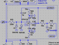
but the advised transformer voltage (with no pre-PSU that includes damping is, as you note) 18Vac, giving 24 to 25Vdc on the PSU.3: That may be a point where we need to improve the design a bit, it would be better, in hindsight, to add a few 10 Ohm resistors in the opamp supply lines (as I normally do) (see attached schema partial).
4: Yes
Your experience makes me think that we have to change the specification for the power transistors. Let’s see what happens when the RIAA is connected.
Attachments
Well, I avoided the film bypasses on the lytics and it worked...Is it the alternative fast transistors that tamed it or is it something with the lytics being bypassed several times over the long phono rails introducing tank circuits that help setting it off? Just a thought.
2: Yes, again it’s know
Meaning to say, any temperature below 60c, in a 20c environment, is acceptable for me, but may be seen as a little bit high by others
. That will lead to 80c in a, high summer, 40c environment (may be seen as borderline, but 40c environment is also borderline (do not switch on those big class-A power amps ).Well, I avoided the film bypasses on the lytics and it worked...
You are saying, you did not stuff C91, C92 and C93? Or you did not place C93 (but placed C91 and C92)? Just to be clear on this.
Is it the alternative fast transistors that tamed it or is it something with the lytics being bypassed several times over the long phono rails introducing tank circuits that help setting it off? Just a thought.
Maybe this could be tested by not stuffing C91, C92 and C93, then (when tested) add C91 and C91, and then after testing, stuff C93. WOuld you do that?
Let’s see what happens when the RIAA is connected.
Will let you know about that soon. I will use no 1uF caps on the rails. Only C93 is already there, across not on, of course for the integrator. And I can remove that if something will ring so to see about it.
I used C93 0.1u ok (No C91 or 92)You are saying, you did not stuff C91, C92 and C93? Or you did not place C93 (but placed C91 and C92)? Just to be clear on this.
Just did not bypass C3 C4 C6 C7
Last edited:
- Home
- Source & Line
- Analogue Source
- Paradise Builders