Thanks. Sorry, yet another question - the PS is made of leftovers, so I have 2 4700uF and 2 1000uF per rail in that order. Is it ok to do the CRC 4700-R-4700-1000-1000 or does it have to be 4700-1000-R-4700-1000 (which means I have to shuffle caps).
Regards
Sven
A nice even split will be best (worth the effort
") )
)@Abraxas
Maybe you can use a higher tap of the primary of the transformers?
(220> 230 or 240 V??) Of course you may not have this possibility ....
There is a bonus in adding the resistive filtering
but yes this is possible too.That's mine,
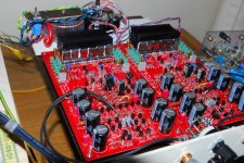
My Paradise "power-on",
PSU minimalist " à la Frans" (FdW), only one Tr (2x20Vac) & 2x2x1N4007, 2x2x10.000micro .... in spider web (point to point).
Hum ..... "no hum", only with my head in the horn(-s) I can hear in sourdine 100 times Mr Hertz .... (a cheap solution).
RIAA matched (& nominal) left & right C/R ...
First music test with (very old) card Ortofon SL20E ...
.... It's music ... I love it ...
My grandchildren loves the "high efficiency" leds (mégacool Opa)... & with a WAF= 10/10.
Now I can start for the "serious" (heavy) static PSU (2 Tr, high Qspeed diode, selfs in spiderweb) ...
Thanks to Joachim (father superior in Paradise), Frans (with his enormous "power"), Alfred (my "guide" in the Paradise archives) ... SQ225917 (with his quick "emergency" help) .... and, sorry, thanks to "all" the Paradise believers (from design to delivery & home builders) for the effort & tech input ....
I think ... I am in Paradise .....
Allez, salukes ..
Karel
Attachments

Not yet, Alfred but on my way.
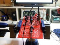
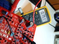
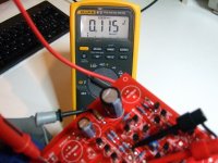
I now added some Rs to my Cs and the rails came down to 26,2V. Heat sink still goes up to >62°C, though.
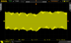
I scoped the 4 regulator voltages. 3 of them look similar to this:
Y div is 1mV. And one looks like this:
This one is significantly higher.
Wenn I started the regs the first time one side of LEDs of one channel didn't light up, I checked and noticed I shortended two legs of either the J310 or BC327, don't remember. Could be that channel - any ideas?
BTW, I already installed the 4 caps according to the assembly guide.
Regards
Sven
I now added some Rs to my Cs and the rails came down to 26,2V. Heat sink still goes up to >62°C, though.
I scoped the 4 regulator voltages. 3 of them look similar to this:
An externally hosted image should be here but it was not working when we last tested it.
Y div is 1mV. And one looks like this:
An externally hosted image should be here but it was not working when we last tested it.
This one is significantly higher.
Wenn I started the regs the first time one side of LEDs of one channel didn't light up, I checked and noticed I shortended two legs of either the J310 or BC327, don't remember. Could be that channel - any ideas?
BTW, I already installed the 4 caps according to the assembly guide.
Regards
Sven
Success!
Well, partially
An externally hosted image should be here but it was not working when we last tested it.
Nice Styroflex RIAA caps! They're Philips right?
Pierre
Finished a channel today powered by a bench linear supply. Which is stable and clean enough for taking measurements. The current draw is 70mA per side and the preamp gains about 62dB @ 1kHz. Can zero the input for DC but the output hops about the zero point. Between +/-30mV most of the time, but has wayward periodic moves also. I could pick its momentary min and max DC offset and there is also a very slow deep memory scan I captured on the scope for you to see an averaged move of signal area about DC level over enough time.
While all the DCV bias test points are closely symmetrical for +18.2V and -18.16V PSUs, I get 0.1V asymmetry across sides of the 82R. Is that in acceptable range?
A spot check on the Riaa curve at 1kHz and 10KHz indicates my build is +0.4dB treble hot VS textbook for 11n and 9K1 I used (measured on LCR). I will have to fully verify the curves with FFT in another time. The DCV on main output concerns me especially when it can overshoot 3.55V at power on and has a long & high DC cycle at power down. Now where is that DCB1 & F5 system to hook it up when I am bored with some badly chosen woofers?
Attachments
Wenn I started the regs the first time one side of LEDs of one channel didn't light up, I checked and noticed I shortended two legs of either the J310 or BC327, don't remember. Could be that channel - any ideas?
If the J310 has been shorted, then the BC327 will be damaged.
Hi SalasFinished a channel today powered by a bench linear supply. Which is stable and clean enough for taking measurements. The current draw is 70mA per side and the preamp gains about 62dB @ 1kHz. Can zero the input for DC but the output hops about the zero point. Between +/-30mV most of the time, but has wayward periodic moves also. I could pick its momentary min and max DC offset and there is also a very slow deep memory scan I captured on the scope for you to see an averaged move of signal area about DC level over enough time.
While all the DCV bias test points are closely symmetrical for +18.2V and -18.16V PSUs, I get 0.1V asymmetry across sides of the 82R. Is that in acceptable range?
A spot check on the Riaa curve at 1kHz and 10KHz indicates my build is +0.4dB treble hot VS textbook for 11n and 9K1 I used (measured on LCR). I will have to fully verify the curves with FFT in another time. The DCV on main output concerns me especially when it can overshoot 3.55V at power on and has a long & high DC cycle at power down. Now where is that DCB1 & F5 system to hook it up when I am bored with some badly chosen woofers?
IMO, when using a 9k1 resistor the 11n cap should be raised to 11.98 (12nF)
The 33.3n cap should alo be increased to 34.95 (35nF).
We can neglect miller effect because the output stage is a buffer.
The bass resistor needs some down trimming also to avoid bass rise below 100Hz
Finished a channel today powered by a bench linear supply. Which is stable and clean enough for taking measurements. The current draw is 70mA per side and the preamp gains about 62dB @ 1kHz. Can zero the input for DC but the output hops about the zero point. Between +/-30mV most of the time, but has wayward periodic moves also. I could pick its momentary min and max DC offset and there is also a very slow deep memory scan I captured on the scope for you to see an averaged move of signal area about DC level over enough time.
While all the DCV bias test points are closely symmetrical for +18.2V and -18.16V PSUs, I get 0.1V asymmetry across sides of the 82R. Is that in acceptable range?
A spot check on the Riaa curve at 1kHz and 10KHz indicates my build is +0.4dB treble hot VS textbook for 11n and 9K1 I used (measured on LCR). I will have to fully verify the curves with FFT in another time. The DCV on main output concerns me especially when it can overshoot 3.55V at power on and has a long & high DC cycle at power down. Now where is that DCB1 & F5 system to hook it up when I am bored with some badly chosen woofers?
hahaha, thats a good one!
Yes you are up and running, the DC movements should come down over time, but yes they appear to be part of Paradise, albeit very low frequency. Suggest to let it settle for a couple weeks and take another look. Have you tried it in your system, what's the sound?
Hi Salas
IMO, when using a 9k1 resistor the 11n cap should be raised to 11.98 (12nF)
The 33.3n cap should alo be increased to 34.95 (35nF).
We can neglect miller effect because the output stage is a buffer.
The bass resistor needs some down trimming also to avoid bass rise below 100Hz
I already have 34.7nF cap. Another 1nF FKP2 it can only be installed underneath the "treble" caps area, its tiny and it can go there. A parallel to trim down the "bass" resistors combo can be botched up easily also. But lets finish the whole and listen to it with originally intended bit "loudness" curve first.
hahaha, thats a good one!
Yes you are up and running, the DC movements should come down over time, but yes they appear to be part of Paradise, albeit very low frequency. Suggest to let it settle for a couple weeks and take another look. Have you tried it in your system, what's the sound?
Its a dangerous situation if there is way for the DC to pass a system chain and get boosted. Especially in non informed hands hooking it up here and there and powering up and down randomly it can blow things up. It either needs an output coupling capacitor or a turn on/off safety output relay and tighter operational drift. Luckily I got a bootstrapped 6V6 valve buffer pre with a Teflon cap at input and I will be able to finish & listen to it without further additions as soon as I will get couple of small electrolytics values hopefully in 105C and the BJT semis I need for its local PSUs. Can I use MJE15030/MJE15031 that I already got instead of the D44H11/D45H11?
Can I use MJE15030/MJE15031 that I already got instead of the D44H11/D45H11?
Yes MJE15030/MJE15031 will do fine.
hi Salas, please just go ahead with the values as published. The output voltage will show low frequency fluctuations of ~100mVpp upon first turn on, and when the whole thing settles that voltage will come down.
This voltage is driven by the low frequency noise of the input dransistors, forming of the 6800uF elcaps, and thermal variations around the input stage. If it is too much, you could e.g. reduce the capacitor of the servo. Reducing the 150k resistors R43a/b is only necessary when there is too much (DC) offset in the amplifier, and the servo output (pin 6) is very high.
If the remainder of your system is not DC coupled, you should have no issue whatsoever.
hope that helps.....
I did a couple of experiments about the offset issue. First I installed a 1K trimmer parallel to the 82R servo correction injection point. That could reduce the min max instantaneous peaks when playing and the power-on huge peak, both by far. But it could not do much for the average +/-30mV I had before. One bad hint was that the channels current draw tended to ask for 10-20mA more when the trimmer was homed in. So I took it out. Then I put 10K resistors in parallel to the 150K ones. That dropped the play at about +/-4mV max but the power-on peak is again there in the volts. The power-off DC ramp down is still there in the hundreds of mV.
I have now fixed the "noisy regulator rail" by exchanging Q102 and Q104. Even though the transistors tested without problem after I removed them the channel is now down to 2mV like the other three.
Frans though it might be worth mentioning here that I did not have to remove my heat sink because of a "precaution" I took for such occasions - I mounted it on 5mm spacers and as a result i do not have to remove it to access the parts underneath it.
The spacers are standard stuff available in all lengths.
Regards
Sven
An externally hosted image should be here but it was not working when we last tested it.
An externally hosted image should be here but it was not working when we last tested it.
I have now fixed the "noisy regulator rail" by exchanging Q102 and Q104. Even though the transistors tested without problem after I removed them the channel is now down to 2mV like the other three.
Sven, "end well, all well". This is the first time I have seen proof that the BC's are actually making the thing oscillate, who would have thought. Still we do not know why (I’m still thinking too much gain), or what the defect is (tiny Nano bots not observing stop signs on level crossings).
I need to tell (let you all know) that this was not the same problem as earlier, which was fixed by adding the compensation capacitors. It was a 'new' phenomenon, and well documented by Sven.
So it goes, you learn something every day, a perfectly (measured) functioning BC can exhibit bad behavior.
It still is probable/possible that it relates to the, earlier fixed, oscillation problem (in fact it may be the source). A bad behaving device could easily ‘ignite’ oscillations, if the circuit is ‘on the brink of’ instability/insanity (and that is fixed by adding the compensation capacitors). Now the same oscillation shows itself as a 12mV noise signal. My, for now provisional, conclusion is; some BC’s are badly behaving and ‘ignite’ oscillation’s. This may also be the explanation why not all PSU’s are oscillating.
Just some thoughts
More information here http://www.direct.gov.uk/prod_consu...n/@motor/documents/digitalasset/dg_191922.pdf
Last edited:
- Home
- Source & Line
- Analogue Source
- Paradise Builders