Thanks Alfred, can you post a picture how it is implemented if it is not too much trouble?
Quan
sure no problem, this will take a couple days as I am busy but I will include this
O.k. to 4 decimals")

Right, but whats that -4V at V+ 6800uF about?
What might be wrong?
Right, but whats that -4V at V+ 6800uF about?
What might be wrong?
Libby123, I do only answer questions regarding the PSU. And at some moments that is a day-job in itself.
Right, but whats that -4V at V+ 6800uF about?
What might be wrong?
could the PNPs be broken? Please check the voltage across R5 and R14 (both ends each, please), thanks
could the PNPs be broken? Please check the voltage across R5 and R14 (both ends each, please), thanks
So I took it.
TP5 and 6 both are 16,55V
TP9 and 10 both are -16,08V
with the 2 220Ohm resistors the upper one (next to J310) -15,32V
the lower one (next to 1M R) -18,11V
Libby123, I do only answer questions regarding the PSU. And at some moments that is a day-job in itself.
Oh, sorry. this should not be critisism. PSU is fine. But big Thanks for help.
Oh, sorry. this should not be critisism. PSU is fine. But big Thanks for help.
Do not worry, it was just to state my 'purpose' here, no critique was taken
So I took it.
TP5 and 6 both are 16,55V
TP9 and 10 both are -16,08V
with the 2 220Ohm resistors the upper one (next to J310) -15,32V
the lower one (next to 1M R) -18,11V
OK thanks. That was not what I was looking for, but helpful. It looks like you have a huge imbalance in the input stage, that cannot be explained with transistor mismatch alone. Can you please check the emitter voltage of Q29 / Q26 / Q25 / Q2 to GND?
While you are at it, please also measure the emitter voltage of the NPNs (Q32 / Q31 / Q30 / Q1)? many thanks
The voltage of Q29 / Q26 / Q25 / Q2 is always -3,8V and Q32 / Q31 / Q30 / Q1 is -4,8V.
The voltage of Q29 / Q26 / Q25 / Q2 is always -3,8V and Q32 / Q31 / Q30 / Q1 is -4,8V.
sorry but thats impossible. is the input shorted, or connected to GND with a low ohmic resistor? Then, the emitter votlage is the voltage from the connection between transistor and 33Ohm resistor, to GND / simply put the black cable of the DMM to Ground, and use the red cable to check all 8 emitter voltages..... thanks a lot and sorry if I have not said clearly enough whats needed...
sorry but thats impossible. is the input shorted, or connected to GND with a low ohmic resistor? Then, the emitter votlage is the voltage from the connection between transistor and 33Ohm resistor, to GND / simply put the black cable of the DMM to Ground, and use the red cable to check all 8 emitter voltages..... thanks a lot and sorry if I have not said clearly enough whats needed...
Yes it is realy impossible, but I took the Voltage like you sais Dmm Black to GND and the red one to emitter. And all trannies are right (327= 327 and 337=337. And all Pimpels look upwards to vplus TP.
Yes it is realy impossible, but I took the Voltage like you sais Dmm Black to GND and the red one to emitter. And all trannies are right (327= 327 and 337=337. And all Pimpels look upwards to vplus TP.
You have not confirmed that the positive input is shorted to ground as requested by Hesener. Is it?
You have not confirmed that the positive input is shorted to ground as requested by Hesener. Is it?
Sorry, I think it is not. I will measure.
But how will it be? could the trimmer do this?
Sorry, I think it is not. I will measure.
But how will it be? could the trimmer do this?
Q29 / Q26 / Q25 / Q2 is always -3,8V
If this were true, the input voltage should be around -4.5V (the VBE of the PNPs and the 3.8V)
....and Q32 / Q31 / Q30 / Q1 is -4,8V
If this were true, the input voltage should be around -4.1V (the VBE of the NPNs minus the 4.8V).
Now, both of above conditions could happen at the same time, but only at a input voltage of e.g. -4.3V or so. It takes an odd combination of issues for that to happen....
could you please check R1 and R1b (the 10k resistor and the input offset trimmer), if they are not short-circuited or causing a short to a negative voltage somehow?
and, can you please check the collector - emitter voltages of the PNPs? That should be around 13V.
And, just for completeness, please measure the voltage on both ends of R5 (82 Ohms) just to see if the current source is operating correctly....
No worries, we'll get there....
If this were true, the input voltage should be around -4.5V (the VBE of the PNPs and the 3.8V)
If this were true, the input voltage should be around -4.1V (the VBE of the NPNs minus the 4.8V).
Now, both of above conditions could happen at the same time, but only at a input voltage of e.g. -4.3V or so. It takes an odd combination of issues for that to happen....
could you please check R1 and R1b (the 10k resistor and the input offset trimmer), if they are not short-circuited or causing a short to a negative voltage somehow?
and, can you please check the collector - emitter voltages of the PNPs? That should be around 13V.
And, just for completeness, please measure the voltage on both ends of R5 (82 Ohms) just to see if the current source is operating correctly....
No worries, we'll get there....
I´ll do. But all at a time (I am still at work).
Sure we will get it.
How do you implement input loading switch if you don't mind me asking?
Quan
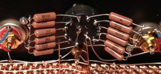
Here you go.... Not fancy but does the job nicely. Resistors are Dale RN65 (10 / 100 / 220 / 470 / 1000 / 2200), the switch is from C&K with silver contacts.
Attachments
Keith, stick a star ground point in your psu box. You'll connect the the middle of each Hacker cap board directly to this for the power earths. You'll run a chasis gnd to it as well from each box and there will also be your tonearm earth and potentially turntable chassis earth. Just make sure the tonearm earth is lifted with a 10 ohm resistor and small cap as per the schematic. Also make sure the gnd on each signal line doesn't get continuity with the amp chassis, keep them seperate.
Feel free to pop over and take a lot at mine this weekend if the snow clears.
http://farm9.staticflickr.com/8220/8414701561_a30d557534_h.jpg
Feel free to pop over and take a lot at mine this weekend if the snow clears.
http://farm9.staticflickr.com/8220/8414701561_a30d557534_h.jpg
Here you go.... Not fancy but does the job nicely. Resistors are Dale RN65 (10 / 100 / 220 / 470 / 1000 / 2200), the switch is from C&K with silver contacts.
Ok thanks Alfred, like they say -" a picture worth a thousand words". Just need to source the rotary C&K switch. I am still getting hum from my R3 , it is playing beautifully just need to get rid of it as it is obscuring the details. I will post a picture and ask for some advice.
Quan
- Home
- Source & Line
- Analogue Source
- Paradise Builders