Whilst on the subject of swaps...
In my GB bag i did not receive any 147K resistors but I did get 4x 2k resistors that I don't think are anywhere on the boards. I also received 16x 150k when I only needed 4x.
Did anyone get more 147k than they needed and could they swap with me or if you don't need any swaps could you send me their spare 147's please?
Does anyone have any spare Dale 147k that I could buy from them please.
Hello,
I would be very happy if anyone of you finds the time to check the values of Joachims schematic or can verify them.
Can you try to simulate JG's circuit?
My testing transformators are only nominal 2x24 volts but I think there is something wrong?
I do not want to burn my Paradise,
Thank you very much,
Christoph
I also have plus/minus 81,5 V AC between plus/minus vdc and ground and
163 V AC between plus vdc and minus vdc
Please explain.
Do you mean you measured AC volts after the rectifiers ?
The circuit you are using is very good... there is no way you can get AC after the rectifiers.
You posted you measured 27 AC volts before the rectifiers... that would give you 37VDC after the rectifiers.... seems ok but as the paradise runs with 18VDC, the shutnts will need to "burn" 20VDC n heat.... maybe you should "loose" some volts with an RC circuit.
Hello Joachim,
I have built a nice necklace from 8 resistors and it adds up to 540 R and
put it in parallel to the outputs plus vdc and ground.
Now I measure between plus vdc and ground 29,7 V DC and 64,3 V AC.
Regards,
Christoph
can you post a schematic, and show where you are measuring AC after the recitifiers?
Hello Studeb,
thanks for your helping!
Yes, I have ~81v ac between red and black, the same between black and blue.
After putting 540R to red and black I measure ~64v ac in parallel.
"Is the black gound tied to anything, or is it floating"
Sorry, my english is too bad, I'm not sure about "floating",
the black ground is connected like is is in the schematic.
Regards,
Christoph
@Rcruz,
yes, as I said, I measure AC volts after the rectifiers.
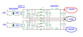
see the schematic:
I have about 81 ac between plus vdc and ground, 163 v ac between plus vdc and minus vdc.
@studeb,
please look at the schematic, it is exactly as I explained it.
Thanks a lot,
Christoph
That is very strange.... can you measure again with a different DMM ?
Maybe your DMM is plying tricks with you

Please check the rectifiers.
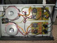
A picture of your setup would help enourmously
Hello Rcruz,
I have no second dmm
First time I try to get some pictures in here
Topside
 [/url][/IMG]
Underside, next time I will do better
 [/url][/IMG]
DC on output
![url]](/community/proxy.php?image=http%3A%2F%2F%5Burl%3Dhttp%3A%2F%2Fwww.diyaudio.com%2Fforums%2Fgallery%2Fshowphoto.php%2Fphoto%2F7868%5D%5BIMGHTTPDEAD%5Dhttp%3A%2F%2Ffiles.diyaudio.com%2Fforums%2Fgallery%2Fdata%2F1775%2Fmedium%2FIMGP2937.JPG%5B%2FIMGHTTPDEAD%5D%5B%2Furl%5D&hash=a6552f304c0e31f660a399ede42d9ac5)
DC across the resistor
![url]](/community/proxy.php?image=http%3A%2F%2F%5Burl%3Dhttp%3A%2F%2Fwww.diyaudio.com%2Fforums%2Fgallery%2Fshowphoto.php%2Fphoto%2F7867%5D%5BIMGHTTPDEAD%5Dhttp%3A%2F%2Ffiles.diyaudio.com%2Fforums%2Fgallery%2Fdata%2F1775%2Fmedium%2FIMGP2936.JPG%5B%2FIMGHTTPDEAD%5D%5B%2Furl%5D&hash=deb327226fabb624be6e66ba3b80d194)
AC across the resistor
![url]](/community/proxy.php?image=http%3A%2F%2F%5Burl%3Dhttp%3A%2F%2Fwww.diyaudio.com%2Fforums%2Fgallery%2Fshowphoto.php%2Fphoto%2F7866%5D%5BIMGHTTPDEAD%5Dhttp%3A%2F%2Ffiles.diyaudio.com%2Fforums%2Fgallery%2Fdata%2F1775%2Fmedium%2FIMGP2935.JPG%5B%2FIMGHTTPDEAD%5D%5B%2Furl%5D&hash=6124306a7881773c1f0c4225a58fa76e)
AC on output
![url]](/community/proxy.php?image=http%3A%2F%2F%5Burl%3Dhttp%3A%2F%2Fwww.diyaudio.com%2Fforums%2Fgallery%2Fshowphoto.php%2Fphoto%2F7864%5D%5BIMGHTTPDEAD%5Dhttp%3A%2F%2Ffiles.diyaudio.com%2Fforums%2Fgallery%2Fdata%2F1775%2Fmedium%2FIMGP2933.JPG%5B%2FIMGHTTPDEAD%5D%5B%2Furl%5D&hash=6bc87456984ef81cec4a9b4715a8d816)
Did some mistakes putting pics in, they are in my photo gallery.
Regards,
Christoph
I have no second dmm
First time I try to get some pictures in here
Topside
Underside, next time I will do better
DC on output
DC across the resistor
AC across the resistor
AC on output
Did some mistakes putting pics in, they are in my photo gallery.
Regards,
Christoph
Last edited:
What are those yellow / black wires coming from the sides of the board ?
What is the AC voltage in the input ? (TX secondaries).
Please build a simple diode bridge, connect it to the TX and make the same measurements... (test the diodes continuity befor build just to be sure they are ok)
If the diodes are ok, and you still measure AC after the bridge... something is wrong with the DMM
Last edited:
If AC input is 27Vac, there is no way you could get 80Vac after the rectifiers.... Something must be wrong with the DMM.
Try loading the output of the board with a 1000ohm and measure the voltage across... then lift one leg of the resistor and measure the current throu it with the dmm.
Try loading the output of the board with a 1000ohm and measure the voltage across... then lift one leg of the resistor and measure the current throu it with the dmm.
If the diodes are ok, and you still measure AC after the bridge... something is wrong with the DMM
If you measure behind a diode bridge there will always be some AC, but it has to be very low compared to the DC, (it's the ripple...). If it's still higher than DC THEN there is something wrong with the Voltmeter.
Mike
Hello Rcruz,
the yellow and blacks are the cables of the chokes.
AC input voltage is 27 v
Tomorrow i will try to build the diode bridge and do the measurements.
Thanks a lot for helping,
Christoph
Just a couple of comments while You fault find on boards nothing major but Paradise is realy good and worth the effort
Can you draw/post SCH of your circuit.
I wuld reccomend you use 2 rectifiers board to suply Pardise
I posted a picture of my BETA PSU the top board uses the same telema common mode cokes
Can you etch your own boards as if you need I can post the PCB lay out as I am using it
Could you get better diodes?
I have posted picture of beta PSU
The AC there as shown by your multymeter is definetley wrong
Attachments
Last edited:
If AC input is 27Vac, there is no way you could get 80Vac after the rectifiers.... Something must be wrong with the DMM.
Try loading the output of the board with a 1000ohm and measure the voltage across... then lift one leg of the resistor and measure the current throu it with the dmm.
There is ....
As you are saying, he has to load output of the power supply board. Plus Vdc vs. ground and Minus Vdc vs. ground with something like 1 kohm - 10 kohm. Without this load, the output capacitors with inductors in series may create resonant circuit and the DMM may either measure voltage on the overcharged capacitor or it is fooled by resonance. With output reasonably loaded, everything should be OK.
- Home
- Source & Line
- Analogue Source
- Paradise Builders