You are welcome Stefan
As soon as I get started with R3 I will make the SMD plug in version but this won't be for a while as is to cold to work in my loft.
The plan is that it wont be much larger than the dip switch and have two rigid pins to solder straight on the board.
And
Tanks Simon
How is it sounding.
Better than my R2 and still giving you monalisa smile while listening to it I supose...
(told you so... )
)
As soon as I get started with R3 I will make the SMD plug in version but this won't be for a while as is to cold to work in my loft.
The plan is that it wont be much larger than the dip switch and have two rigid pins to solder straight on the board.
And
Tanks Simon
How is it sounding.
Better than my R2 and still giving you monalisa smile while listening to it I supose...
(told you so...
)
Last edited:
I'm in Paradise now!
Its running without any hum or hiss, just music!
Thank you all so much for any help and hints,
Christoph
Happy Paradise-ing
@analog_Sa
sorry, I've got no scope, if I had one I would have no idea how to use it.
First impressions is, I am jumping around, grabbing my favourite records, listen to them one after another, I can't find faults on the performance of the Paradise. It is inviting and is pushing all the time.
Compared to my Volpe, which I like very much, it seems that I have a slightly more depht, a little more punch in the bass, some grace when playing records, which are not first grade.
I'm just listening to a live record of Townes van Zandt, recorded in Berlin late 1990, called "Rain on a conga drum", I love this recording, it is very narrow and authentic.
Thank you all,
Christoph
Now the voltage is -0,698V on the upper resitor block (going down to vminus) and +0,697V at the lower one (going up to vplus). Me think it´s alright now.
But now another problem. I start up a soundcheck. Everything alright but there was a little fizz in voices. So I recheck the riaa area. I have 33.3nF at one bench (horizontal bench) (matched very good
I looked on the shematic and this could not be. There are only the R18c (Neumann) and C2a and C2b that go to Vriaa. Right? That would mean ground to VRIAA is Capacity of 25,4nF.
Thanks
Good news, at least from a DC point of view you are up and running...
The circuit node where the RIAA caps go is very high impedance, there should be very little capacitance there. Thats strange.....
I'm in Paradise now!
Its running without any hum or hiss, just music!
PSU under the Trio/Kenwood,
Paradise on the left:
Thank you all so much for any help and hints,
Christoph
Great news, and beautiful casework!!!
PSU compensation caps
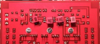
Hi all,
here a picture of how the compensation caps in the PSU can be applied, you need to locate the transistors under the heatsinks (the footpritns with the three connections), and solder the caps between the innermost and the middle pin. The transistors closer to the corners should get 470pF, the inner transistors 2.7nF.
On the picture you will see 3.3nF caps - before you ask , that is simply because I had them on hand
Many thanks to Doppelkopf who kindly lent me his boards so I could play with them..... After the PSU fix (yes they were oscillating) they sounded nice, with the groove JG/MiiB house courve....
Attachments
After the PSU fix (yes they were oscillating) they sounded nice, with the groove JG/MiiB house courve....
Do you have a scope trace of the output to show?
no high frequency there. I remember though that when I was measuring in our lab, there were traces of other stuff (22kHz from a fluorescent lamp, 65kHz from power supplies etc etc) visible. The lab I have at work certainly is not the most quiet place, and this amplifier requires shielding to excel ....
Here http://www.diyaudio.com/forums/analogue-source/218625-paradise-builders-118.html#post3334606 you can see some 600~700uVpp (I would guess near 200uVrms) noise embedded in sampling artifacts of the scope. IMHO this noise is all/most due to fact that the PSU is operating unshielded. This all is at the measuring limit of the scope.
Noise is random not sinusoidal. Its either something produced in the circuit or in the environment picked up by it and/or the measurement loop.
Here http://www.diyaudio.com/forums/analogue-source/218625-paradise-builders-118.html#post3334606 you can see some 600~700uVpp (I would guess near 200uVrms) noise embedded in sampling artifacts of the scope. IMHO this noise is all/most due to fact that the PSU is operating unshielded. This all is at the measuring limit of the scope.
The sinusoidal signal is 5nS and is the scopes sampler triggering on the noise, you can filter this out, but then the signal is even more hidden. When you remove this sinusoidal (using imagination or Photoshop
) from the shown signal part then to will be left with about 700uVpp of random noise.The main problem here (if it where a problem) is that the scope is on/over it's practical limit, and it is the best one (scope) that I have
One other 'problem' is me
getting acquainted with the scope (more learning to do).
Last edited:
My paradise is running too.
In the beginning, I get PSU oscillating, add 4.7nF and 3.3nf compensation caps to solve it; then I have offset issue, the offset was fluctuating +/-200mV.
First, I used the 500R to trimming R15 but nothing change, after I reduce R43a/R43b to 9.1K then the offset was stable in between +/-20mV (change to 3.9K could down to +/-5mV)
I can see about 800uV of noise on my scope, I only used one transformer but LCLC filtering.
Will keep it to power on for stable, will listing it this weekend.
Regards,
jj
My paradise is running too.
In the beginning, I get PSU oscillating, add 4.7nF and 3.3nf compensation caps to solve it; then I have offset issue, the offset was fluctuating +/-200mV.
First, I used the 500R to trimming R15 but nothing change, after I reduce R43a/R43b to 9.1K then the offset was stable in between +/-20mV (change to 3.9K could down to +/-5mV)
I can see about 800uV of noise on my scope, I only used one transformer but LCLC filtering.
Will keep it to power on for stable, will listing it this weekend.
Regards,
jj
Nice, one more
happy Paradise-ing!- Home
- Source & Line
- Analogue Source
- Paradise Builders