I thing the problem is the common ground of the boards in combination with grounding the input.
Chris
Try a "star" ground at the input connector of the phono preamp, where you take the turntable ground, and isolated metal "bath tubs" for both boards, also connected to the same star ground, that should solve it. You can use double-sided sticky tape to mechanically fix the bath tubs.
We added the input offset trim " just in case", to erode even the tiniest amount. A well build Paradise does not need the offset trim and cartridges can be swapped at will.
What happens here is typical. We have discussed this in detail before but for late comers going throw nearly 10,000 posts is hard.
What happens here is typical. We have discussed this in detail before but for late comers going throw nearly 10,000 posts is hard.
Many (DIY and professional) MC phono pre's are on the market, with DC coupled inputs, and this seems to be a non-issue. In fact, I asked that question over at John Curl's "Blowtorch" thread, and the experts commented that they never saw this as an issue (PMA you may remember as you were one of the experts replying to this).
Hi hesener,
yes I agree with your post. In 2008 I was asked to design a MC preamp. It was completely DC coupled. There was a small-lot production of that phono preamp, like 50 - 100 pcs. None of the preamps produced had problems with DC offset fluctuation, in other words all were stable and output DC offset voltage was like 1 - 2mV or less, depending on ICs used. The preamp was similar to my MM open project with linear 20dB stage added in front of the MM input terminals.
Regards,
Try a "star" ground at the input connector of the phono preamp, where you take the turntable ground, and isolated metal "bath tubs" for both boards, also connected to the same star ground, that should solve it. You can use double-sided sticky tape to mechanically fix the bath tubs.
It´s more entertaining to hear perfect music with both psu as finding the right grounding with one, but i try it at the evening.
")
Chris
all were stable and output DC offset voltage was like 1 - 2mV or less, depending on ICs used.
Regards,
many thanks, thats exactly what we should expect here as well, the remaining offset being the normal offset for a IC opamp without nulling. the proposal from sq225917 makes perfect sense in that context.
I saw your circuit before, but the ground of both boards are common, only the ground of the turntable is decouples through DDRC, right? Chris
Yes you are
still I would like you to try it (if posible) (it will/may help other people in the future). Having the DDRC in the player will (IMHO) harm nothing.Also, the schema as shown makes sure that the -L and -R of the cartridge are separated (all the way) and that the player ground and signal-ground (the arm) are separated (you need one extra wire from the player to the RIAA).
After that all grounds are connected at a 'star'-point in the RIAA-box.
Maybe RCruz has a thing (or two) to add on this subject
Last edited:
Yes you are
I try it
Chris
For the sake of keeping everything together i would like to list my "symptoms" once again, so builders with similar issues will be able to recognise them.
Hfe at input was in the region of 500 and elsewhere in the range 450-480
47ohm at input, both channels powered from a single dc source but no common ground connections other than a star in the PS.
1. With servo on i get a bipolar offset voltage with about 200mV of amplitude and about 0.5Hz in frequency. This is obviously averaged by my Fluke 73 voltmeter.
2. Without the servo, offset has an amplitude of about 4v under the same conditions.
4. High frequencies: a few mV at output which look like a 7-8MHz signal but may just be white noise
3. Shorting the input produces full scale oscillations at output - i am very curious how do the "good" builds behave under shorted input
4. Both channels behave very consistently.
After Hesener's remark that the boards may interact, powered one board down with no effect on the other.
At present i have left this on for the next 48 hours. If after that time the offset has miraculously settled down to 2mV i hereby solemnly promise to eat my GF's shorts.
I can increase the LF outputoffsetfluctuation by blowing to the pcb .
The offsetfluctuation is also higher with the 20kOhm on output than without .
I will check to support R15 by a Trimmerpoti when i get one .
The inputoffset is stabil , so the shunt is.
Just what I was looking for and possible improvment on the orizon
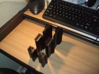
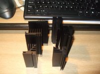
I am not saiing that a separate psu board may make an improvment also I am not saiing that a different heath sink may also help.
No not saiing this at all till I tried and psosted pictures to prove it
And an old post by Sallas came to mind....
Sumtink to do with thermal coupling
And then another big one burried away about using highest possible Hfe for imputs which may also improve spatiality.
Attachments
I thing the problem is the common ground of the boards in combination with grounding the input.
Chris
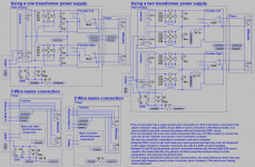
If you use only one TX to power both board, then both boards share a common ground... in this case you should not connect also both input grounds together otherwise you have a ground loop.
Try a "star" ground at the input connector of the phono preamp, where you take the turntable ground, and isolated metal "bath tubs" for both boards, also connected to the same star ground, that should solve it. You can use double-sided sticky tape to mechanically fix the bath tubs.
This will work if you use two independent psu´s one for each channel, and the only common connection is at the star in the input.
Also, the schema as shown makes sure that the -L and -R of the cartridge are separated (all the way) and that the player ground and signal-ground (the arm) are separated (you need one extra wire from the player to the RIAA).
After that all grounds are connected at a 'star'-point in the RIAA-box.
Maybe RCruz has a thing (or two) to add on this subject
IMO the best solution is to connect TT chassis to arm gnd to amplifier chassis and all these to earth GND using a DDCR (or DDR).
I also connect signal gnd to chassis gnd using a 10r.
Attachments
One link that I found may (or may not) be helpfull:
http://www.rsgb.org/emc/docs/pdf/leaflets/emc-leaflet-07.pdf
As I look at it, the usage of the DDCR changes the relation between the player and the RIAA to a 'TT'-grounding configuration (from a TN-S/TN-C-S configuration (sort of)).
http://www.rsgb.org/emc/docs/pdf/leaflets/emc-leaflet-07.pdf
As I look at it, the usage of the DDCR changes the relation between the player and the RIAA to a 'TT'-grounding configuration
(from a TN-S/TN-C-S configuration (sort of)).
Last edited:
Even more reading:
www.acoustica.org.uk on mains spurs
www.acoustica.org.uk on mains spurs (earth (not the planet))
p.s. These are two different url's
www.acoustica.org.uk on mains spurs
www.acoustica.org.uk on mains spurs (earth (not the planet))
p.s. These are two different url's
Last edited:
Grounding
Just tested consistently grounding on one starpoint with one psu, only one connection from the boards to the startpoint.
With plugged dummys i had light hum, but with plugged DL 103
maximum hum. Pluging input ground from the starpoint to the boards, hum change into noise, same as at my first try.
I use a DIY tonarm (Schröder Clone) with a DIY cable.
The paradise works fine with two psu and thats my choise, I will test only DDRC for turntable grounding, but also with two psu.
Chris
I'm putting each channel of mine into its own case and the two psu's into another. Any suggestions. i think I might build a couple of DDCR tonight.
See 'Using a two transformer PSU' in the schema of post#894 http://www.diyaudio.com/forums/analogue-source/218625-paradise-builders-90.html#post3314964
1. With servo on i get a bipolar offset voltage with about 200mV of amplitude and about 0.5Hz in frequency. This is obviously averaged by my Fluke 73 voltmeter.
A large part of this is, as some contributors already mentioned, temperature dependent. I covered the input transistors with a strip of copper foil smeared with heatsink compound and the output twitchiness came down quite a bit . There must be a better solution to this but as a temporary measure i'll be looking for temperature conducting glue and maybe reducing the timeconstant of the servo. Any ideas how to encase the input devices together? Would this not indicate that high Hfe devices should be avoided in the input circuit as they are surely more prone to temperature variations?
- Home
- Source & Line
- Analogue Source
- Paradise Builders