Hello guys and a happy and healthy new year.
Yesterday I found a little time to try a first seating test in the enclosure,
I have taken 2 pics
![url]](/community/proxy.php?image=http%3A%2F%2F%5Burl%3Dhttp%3A%2F%2Fwww.diyaudio.com%2Fforums%2Fgallery%2Fshowphoto.php%2Fphoto%2F7878%5D%5BIMGHTTPDEAD%5Dhttp%3A%2F%2Ffiles.diyaudio.com%2Fforums%2Fgallery%2Fdata%2F1775%2Fmedium%2FIMGP2962.JPG%5B%2FIMGHTTPDEAD%5D%5B%2Furl%5D&hash=3886dca6956af601bac103ea292d3726)
I beg you all to have a look at my posting #682, where I told of my 3 problems. I have no idea what to do to fix them.
I truly like to run my paradise,
regards,
Christoph
Yesterday I found a little time to try a first seating test in the enclosure,
I have taken 2 pics
An externally hosted image should be here but it was not working when we last tested it.
I beg you all to have a look at my posting #682, where I told of my 3 problems. I have no idea what to do to fix them.
I truly like to run my paradise,
regards,
Christoph
Christoph, if the layout you have shown is a MC preamp, it must have hum and buzz like a hell. MC preamp is one of the most difficult audio components regarding wiring, shielding, grounds, pickup of magnetic field from transformers. I hope someone who designed this project would also give some recommendations and construction hints. My hint is to keep the input of the MC preamp as far as possible from any transformer and avoid any loops (loops of analog ground).
Attachments
For those who have Fairchild BC327 and BC337 devices, measurements below show they can be matched with devices from ON Semi purchased from Digikey. Now that this is done, it is time to return to my Paradise build.
border="1" style="border-collapse:collapse;" style="text-align:center"
||hFE*
(mV)
|| BC337-40
Fairchild
NPN
|| BC337-40
ON Semi
NPN
|| BC327-40
Fairchild
PNP
|| BC327-40
ON Semi
PNP
|-
||595-600 || || || || 8
|-
||595-600 || || || || 8
|-
||590-595 || || || || 8
|-
||585-590 || || || || 12
|-
||580-585 || || || || 10
|-
||575-580 || || || || 14
|-
||570-575 || || || || 22
|-
||565-570 || || || || 15
|-
||560-565 || || || || 18
|-
||555-560 || || || || 11
|-
||550-555 || || || || 11
|-
||545-550 || 14 || || || 12
|-
||540-545 || 45 || || || 11
|-
||535-540 || 36 || || || 10
|-
||530-535 || 14 || || || 8
|-
||525-530 || 27 || || || 7
|-
||520-525 || 37 || || || 10
|-
||515-520 || 70 || || || 2
|-
||510-515 || 70 || || ||
|-
||505-510 || 80 || || ||
|-
||500-505 || 36 || || 1 ||
|-
||495-500 || 16 || || ||
|-
||490-495 || || || ||
|-
||485-490 || || || 1 ||
|-
||480-485 || || || 2 ||
|-
||475-480 || || || 1 ||
|-
||470-475 || || || 1 ||
|-
||465-470 || || || 2 ||
|-
||460-465 || || 8 || 1 ||
|-
||455-460 || || 6 || 1 ||
|-
||450-455 || || 10 || 3 ||
|-
||445-450 || || 1 || 3 ||
|-
||440-445 || || 9 || 3 ||
|-
||435-440 || || 8 || 6 ||
|-
||430-435 || || 12 || 10 ||
|-
||425-430 || || 19 || 15 ||
|-
||420-425 || || 6 || 12 ||
|-
||415-420 || || 15 || 27 ||
|-
||410-415 || || 19 || 33 ||
|-
||405-410 || || 21 || 23 ||
|-
||400-405 || || 24 || 22 ||
|-
||395-400 || || 29 || 13 ||
|-
||390-395 || || || 13 ||
|-
||385-390 || || || 19 ||
|-
||380-385 || || || 11 ||
|-
||375-380 || || || 15 ||
|-
||370-375 || || || 22 ||
|-
||365-370 || || || 34 ||
|-
||360-365 || || || 36 ||
|-
||355-360 || || || 38 ||
|-
*hFE approximation using the circuit shown in Post #72. All measurements made at room temperature with fan blowing on transistor.
Happy New Year to all!
Pierre
Did you leave it connected for some time ?Hello guys and a happy and healthy new year.
Yesterday I found a little time to try a first seating test in the enclosure,
I have taken 2 pics
An externally hosted image should be here but it was not working when we last tested it.
I beg you all to have a look at my posting #682, where I told of my 3 problems. I have no idea what to do to fix them.
I truly like to run my paradise,
regards,
Christoph
Output offset should go down after caps settle.
Did you leave it connected for some time ?
Output offset should go down after caps settle.
Do they really need to to "settle"? I guess I have built hundreds of DC servos and caps never needed to "settle". They only needed to charge during RC time constant, this should last no more than seconds with max. like 10s.
Do they really need to to "settle"? I guess I have built hundreds of DC servos and caps never needed to "settle". They only needed to charge during RC time constant, this should last no more than seconds with max. like 10s.
The "settling" that happens is the input caps (elcaps, connected in series with the cartridge and they have DC). It actually is like Ricardo is describing, let them settle (turned ON) for a couple weeks and see what happens
Fun and games...
Just been putting together the first board of a Paradise brace and I'm having a couple of problems.
The power supply side is working fine, providing the +/-18V quite steadily.
I'm measured voltages at the test points as in the pdf for the schematic linked in this thread. The picture below (which may be a little large, but lots of detail!) shows the results.
Shame the text is too small
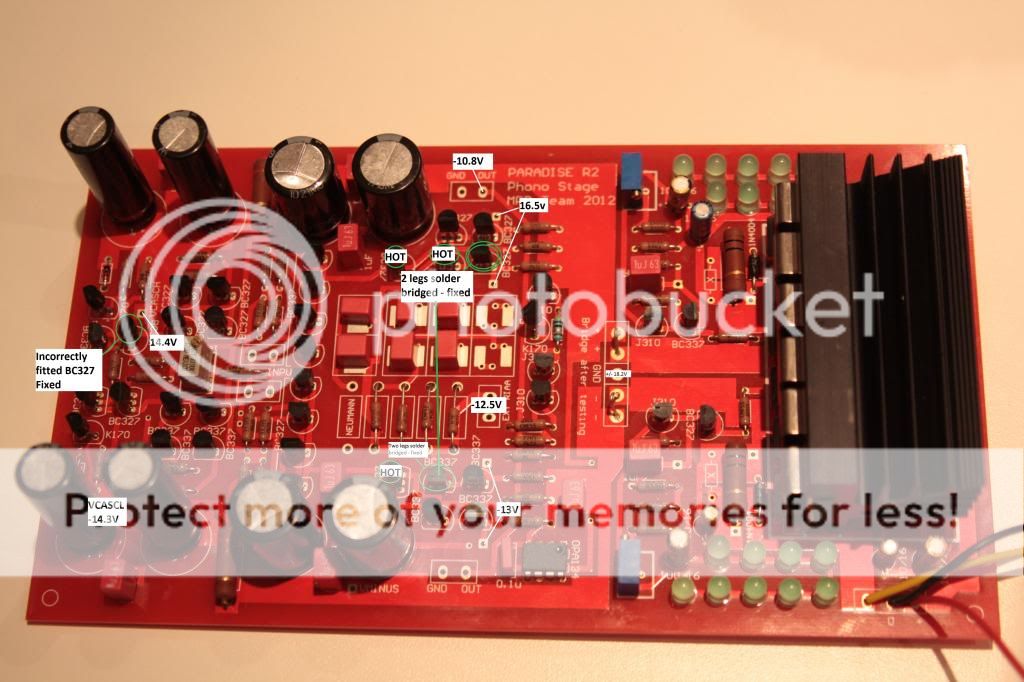
I firstly had a problem with a couple of solder bridges on transistors, I've highlighted those. I did power the board with the bridges in place so the transistors may be damaged. I removed the bridges, but not the transistors.
I misplaced a BC327 instead of a BC337 (Q51 I think - don't know my way around the board yet!). Again, I powered the board before I spotted the problem.
The problems I'm seeing are:
Output is at -10.9v
The EXT RIAA is at -12.5V
TP9/TP10 measure at -13V
Q22 (BC327) and Q18 (BC327) run very hot, can't touch for more than five secs.
Additionally:
TP5/TP6 measure at 16.5V
VCASCH is 14.4V
VCASCL is -14.4V
All three are inline with the published schematic.
I'm tempted to just replace all the transistors in the centre current sources, starting with the BC337, as that is where the voltages are incorrect.
Grateful for any hints and guidance
Thank you.
Just been putting together the first board of a Paradise brace and I'm having a couple of problems.
The power supply side is working fine, providing the +/-18V quite steadily.
I'm measured voltages at the test points as in the pdf for the schematic linked in this thread. The picture below (which may be a little large, but lots of detail!) shows the results.
Shame the text is too small
I firstly had a problem with a couple of solder bridges on transistors, I've highlighted those. I did power the board with the bridges in place so the transistors may be damaged. I removed the bridges, but not the transistors.
I misplaced a BC327 instead of a BC337 (Q51 I think - don't know my way around the board yet!). Again, I powered the board before I spotted the problem.
The problems I'm seeing are:
Output is at -10.9v
The EXT RIAA is at -12.5V
TP9/TP10 measure at -13V
Q22 (BC327) and Q18 (BC327) run very hot, can't touch for more than five secs.
Additionally:
TP5/TP6 measure at 16.5V
VCASCH is 14.4V
VCASCL is -14.4V
All three are inline with the published schematic.
I'm tempted to just replace all the transistors in the centre current sources, starting with the BC337, as that is where the voltages are incorrect.
Grateful for any hints and guidance
Thank you.
Last edited:
but I have ca. 5 V at pin 6 of the opa134 (should be around 0,5 V), on both of my boards.
Don't know how to fix this.
Christoph
thats not a big problem, it is the servo compensating the offset of the amplifier. 5V is high but still within the capabilities of the opamp. I would suggest to let it settle another two weeks turned ON and see what happens, eventually this voltage will come down or at least become stable.
Christoph, if the layout you have shown is a MC preamp, it must have hum and buzz like a hell. MC preamp is one of the most difficult audio components regarding wiring, shielding, grounds, pickup of magnetic field from transformers. I hope someone who designed this project would also give some recommendations and construction hints. My hint is to keep the input of the MC preamp as far as possible from any transformer and avoid any loops (loops of analog ground).
PMA, your advice is good (as usual
). Guys please check the assembly guide, it has my arrangement as an example, worked fine for me and is very low noise. I do use an external pre-regulator (as most of the builders are probably looking at doing anyway).
The "settling" that happens is the input caps (elcaps, connected in series with the cartridge and they have DC). It actually is like Ricardo is describing, let them settle (turned ON) for a couple weeks and see what happens
Thank you for the explanation, anyway it is quite unhappy solution to put elcaps between the cartridge and input of electronic circuits. What is the reason, is there any input bias current flowing into input?? I would always try to avoid elcap coupling capacitors. Sorry to say that but this might be a serious design flaw here and look how the guys complain.
The problems I'm seeing are:
Output is at -10.9v
The EXT RIAA is at -12.5V
TP9/TP10 measure at -13V
Q22 (BC327) and Q18 (BC327) run very hot, can't touch for more than five secs.
Additionally:
TP5/TP6 measure at 16.5V
VCASCH is 14.4V
VCASCL is -14.4V
All three are inline with the published schematic.
I'm tempted to just replace all the transistors in the centre current sources, starting with the BC337, as that is where the voltages are incorrect.
Grateful for any hints and guidance
Thank you.
At first sight, your boards do not have the "NEUMANN" resistors (or wire bridges) in place, check the assembly guide for that function (needs to be either 220OHM or a wire). If not in place ,the RIAA section is floating and that could explain a lot of the problems you are seeing.
Still, it is intriguing why these transistors are getting hot, they should not - everything is connected through current sources or mirrors so that should not happen. Best to check if these transistors are intact.
Thank you for the explanation, anyway it is quite unhappy solution to put elcaps between the cartridge and input of electronic circuits. What is the reason, is there any input bias current flowing into input?? I would always try to avoid elcap coupling capacitors. Sorry to say that but this might be a serious design flaw here and look how the guys complain.
The design concept is from Joachim Gerhard, and the schematic and simulation from MiiB. I just did the layout and group buy, and helping out here with fixing bugs. The design has been extensively discussed over at the MPP thread in all its beautiful glory. It has been proven to sound very nice.
Agree with you on the elcap coupling, however it made the biasing of the input stage much easier in this design and sounds very nice. The only thing to consider is to let the caps settle for some time, that should do it.
Thank you for the explanation, anyway it is quite unhappy solution to put elcaps between the cartridge and input of electronic circuits. What is the reason, is there any input bias current flowing into input?? I would always try to avoid elcap coupling capacitors. Sorry to say that but this might be a serious design flaw here and look how the guys complain.
We do not have any coupling elcap in this circuit... it is dc coupled.
The caps we are refering to are the big (12000uF) emitter caps in the input circuit.
Do they really need to to "settle"? I guess I have built hundreds of DC servos and caps never needed to "settle". They only needed to charge during RC time constant, this should last no more than seconds with max. like 10s.
A full schema can be found here http://www.diyaudio.com/forums/group-buys/216891-paradise-phono-stage.html#post3106817
At first sight, your boards do not have the "NEUMANN" resistors (or wire bridges) in place, check the assembly guide for that function (needs to be either 220OHM or a wire). If not in place ,the RIAA section is floating and that could explain a lot of the problems you are seeing.
Still, it is intriguing why these transistors are getting hot, they should not - everything is connected through current sources or mirrors so that should not happen. Best to check if these transistors are intact.
Thank you for the guidance so far.
But sadly, this is a case of RTFM for me...
Adding the 10K input resistor solved all my problems, are there it is in the assembly guide...I will learn to be a little less impatient, honest I will...
I've managed to get the input offset to zero
The output is moving between -50mV and 150mV on my fluke, I've not had a chance to connect my 'scope as yet...
Last edited:
Dragged my old 'scope out, covered in brick dust from some house alterations...
SEC/DIV is set at .1uS. V/DIV is 50mV.
Interesting output...is this normal?
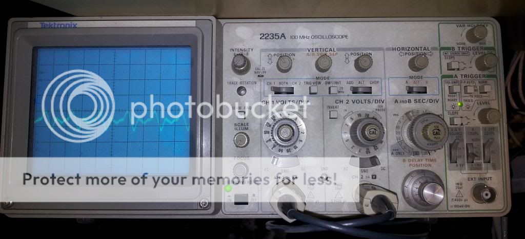
Still seeing a couple of the BC327 (same ones as before) getting hot. I have replace all this group of five BC327s previously.
SEC/DIV is set at .1uS. V/DIV is 50mV.
Interesting output...is this normal?
Still seeing a couple of the BC327 (same ones as before) getting hot. I have replace all this group of five BC327s previously.
Pavel, input and output are DC coupled. The electrolytics are in the biasing circuit of the input stage. They have 3 main jobs to do :
Separating DC bias and AC feedback.
Filtering the bias.
Shunting the noise to ground.
The circuit can also be setup without this elcaps by substituting them with transdiodes that do the DC shifting but then the noise will go up by 3dB and there is no PSU filtering of the bias any more.
This elcaps have an effect on the output DC. My board had 25mV DC at the output initially. That went away after some use. I think the reason is the the leakage current goes down in the elcaps after a while. One way to prevent this is " forming" of the elcaps before they are soldered into the board. That can be done by charging them with with the nominal voltage on a lab PSU for some days.
You can listen to the Paradise though even before this has settled when a film cap is present at the output or if the next stage in the chain is AC coupled. After the offset has come down the film cap can be taken out again.
Dragged my old 'scope out, covered in brick dust from some house alterations...
SEC/DIV is set at .1uS. V/DIV is 50mV.
Interesting output...is this normal?
Still seeing a couple of the BC327 (same ones as before) getting hot. I have replace all this group of five BC327s previously.
According to the settings you have described you have oscillations with 200ns period, that is at 5MHz. This is definitely NOT normal.
According to the settings you have described you have oscillations with 200ns period, that is at 5MHz. This is definitely NOT normal.
I've disconnected the shunt reg and the trace is present on the +18V, -18V and GND pins coming out of the shunt. It is also still present on the GND and OUT pins...is this RFI I'm seeing?
I've read back through the thread and noticed that there was the posting of another trace, some oscillation and also -5V on pin 6 of the servo...I'm seeing that too (though only with the shunt connected!!).
I'm running about 37V into the shunt.
Last edited:
- Home
- Source & Line
- Analogue Source
- Paradise Builders