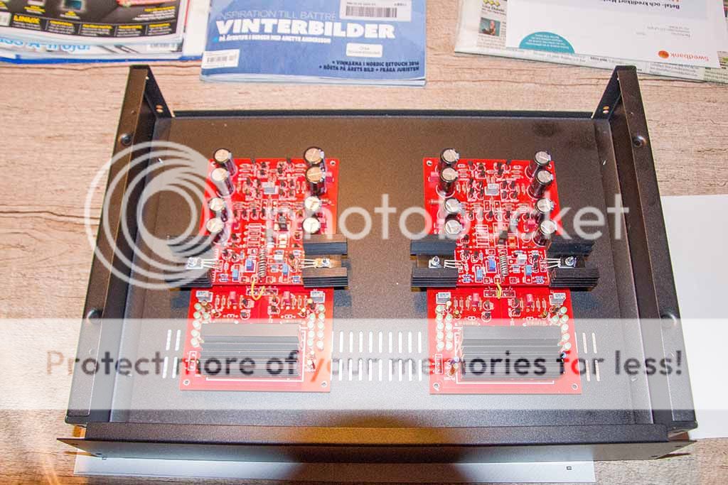
Here is a layoutquestion,if I turn the pcb´s this way so that I get the heatsinks over the (and under the top)ventilation holes.
The back of the box is closest to the camera where the RCA inputs will be.
If I use shielded cable is there any dissadvantage to draw the cable in the middle between pcb´s to the inputs??
There's no hard and fast rule. Some people say having shorter psu input wires is better than having shorter signal cables, I've built Paradise with both but favour the most direct signal cable routing and keeping them away from psu wires wherever possible. See image below.
Longer psu cables will radiate more noise, twisting them will deal with most of this. I prefer to use micro-coax for the signal cables and have had no issues with noise in any Paradise that I've built for people. But then I've never passed the signal cables across the entire pcb.
If you are going to use a ventilated case make sure you build a little house to cover the input stage transistors. A folded U-section of card that runs between the el-caps, covering the 8 input transistors will do the job.
An externally hosted image should be here but it was not working when we last tested it.
Longer psu cables will radiate more noise, twisting them will deal with most of this. I prefer to use micro-coax for the signal cables and have had no issues with noise in any Paradise that I've built for people. But then I've never passed the signal cables across the entire pcb.
If you are going to use a ventilated case make sure you build a little house to cover the input stage transistors. A folded U-section of card that runs between the el-caps, covering the 8 input transistors will do the job.
All the builds I've ever done for anyone else have never used venting, other than natural losses in the sleeved case, which are sufficient. My own case is sleeved in semi transparent acrylic and has vent laser cut directly over the shunt, but there's no venting in the case bottom, it's largely cosmetic. However all my builds are monoblocks so YMMV.
Ok,then I´ll turn the pcb´s around so that I get input near the Rca..
IMHO I'm not so sure about that, it is not advisable to place the input section over the vent holes, the PSU section is better placed over the vent holes.
If you are going to rotate, then consider closing the vent holes, but I would like to see that the PSU gets a bit of air flow.
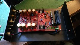
This is how i did mine: 4Y6A8385_zps230da128.jpg Photo by Rolle2k | Photobucket
Although i used shielded power cables from then input to the boards...
Although i used shielded power cables from then input to the boards...
21 so far Alfred. Lots of happy friends and acquaintances.
My apologies for the late reply, thats fabulous - you should be able to contribute a lot to the build guide

And yes, at least I have met pretty much all builders around Munich, I share the appreciation on the friends and acquaintances! Thats a big part of it.....
Paradise cases
My Paradise is in closed boxes. As I build the boxes around them, I never had the feeling the temperature got to hot in there.
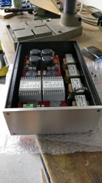
I have been looking for a case for the PSU for a very long time, now it looks like this.
I will measure the internal temperatures next weekend.
As you can see in the PSU, the xformers are installed as "doppelwopper".
I allready bought some other xformers as the "original Block" but still have a lot of mechanical buzzing...Don't exactly know why...Should I try to bring the Xformers on a bigger distance to each other, as they could maybe interfere with each other??
My Paradise is in closed boxes. As I build the boxes around them, I never had the feeling the temperature got to hot in there.
I have been looking for a case for the PSU for a very long time, now it looks like this.
I will measure the internal temperatures next weekend.
As you can see in the PSU, the xformers are installed as "doppelwopper".
I allready bought some other xformers as the "original Block" but still have a lot of mechanical buzzing...Don't exactly know why...Should I try to bring the Xformers on a bigger distance to each other, as they could maybe interfere with each other??
Attachments
... I allready bought some other xformers as the "original Block" but still have a lot of mechanical buzzing...Don't exactly know why...Should I try to bring the Xformers on a bigger distance to each other, as they could maybe interfere with each other??
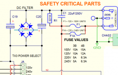
Maybe you need a simple Mains-DC-blocker
Mains DC and Transformers
Hello Frans,
I allready did build the DC blocker from Bryston. My Avantgarde Acoustic UNOs had a incredible loud humming from their transformers at times. I measured some 1,5V DC on the mains!!! There is no industry in the neighbourhood.
After building the DC Blocker the Avantgardes and Tubeamp are completely silent, but the Paradise PSU still humms
Groetjes, Remco
Attachments
The original block transforms were awful, badly wound with poor epoxy potting. The grey ones that you have purchased were the same ones as those I used when I built a Paradise for Markus Sauer (rip) and they were perfectly quiet.
Maybe it is the proximity of the mains input transformers to the chokes?
Maybe it is the proximity of the mains input transformers to the chokes?
A bit offtopic, but still with this design to do - Is there any reason why the common mode choke is at the input on the AC side, instead of between a pair of caps on DC side? Would the CMRR-ratio be worse when it is combined as a CLC-filter?
When i have done my Salas SSLV-boards i did C L C input, with small 120mH common mode chokes between the caps... I know the inductance is pretty much too small for mains frequency - but it is still works as small resistor, instead of using C R C or just a big C-filter...
When i have done my Salas SSLV-boards i did C L C input, with small 120mH common mode chokes between the caps... I know the inductance is pretty much too small for mains frequency - but it is still works as small resistor, instead of using C R C or just a big C-filter...
sq225917,
thanks for your input. I found for snubber in your thread "pre-regboard" these: The values are 10n, 82r +15n (C-RC)
Can I use these to try, as I don't know exact specs from the xformers I use?
Can't hardly imagine it is an interference with the chokes, because, before I put it in the box, these were at quit a big distance.
I have a problem, I have TP9 16,40V and in TP5 14,99V in the other board they are around 14,90 both of them. First board offset is wavering around 20mV but IC pin6 voltage is 14V. and slowly goes down while on the second board it is fixed at 0,626V. 327 andd 337 have been matched with the assembly guide circuit. Any idea?
- Home
- Source & Line
- Analogue Source
- Paradise Builders