Scope draws a flat line at the output.
Shunt neg: -0.558V
Shunt pos: +0.544V
Pre Reg neg: 23.24V
Pre Reg Pos: 23.9V
I'm not sure where you did measure these, can give your voltages as indicated in the attached PDF? The total wattage from the raw-PSU is being disipated in the regulator (about 120mA @ 24V = 30 Watt (more or less)), if the RIAA is not connected it will get very hot. Check the voltage across the two 10 Ohm (R140/204) resistors, it should be 1.2V.
Attachments
Last edited:
It's a bit of an ugly picture on my 60MHz scope but it's definitely oscillation at and above 100MHz. Will try to add ceramic caps. [/QUOTE)
So we have succesfully build a paradise rf transmitter
TP101: 20.048V
TP102: 18.026V
TP103: 24.081V
TP104: 541mV
Vin(pos): 31V@215mA
TP201: -19.498V
TP202: -18.030V
TP203: -23.540V
TP204: -552mV
Vin(neg): -31V@154mA
The PSU seems almost o.k. There is one thing, the difference between TP102 and TP103 is a bit big, setting the current for the positive regulator a bit high (215mA). Best thing is to replace LED110 and Q102, one of those seems to be the problem.
The PSU seems almost o.k. There is one thing, the difference between TP102 and TP103 is a bit big, setting the current for the positive regulator a bit high (215mA). Best thing is to replace LED110 and Q102, one of those seems to be the problem.
I did so. But no change.
I did so. But no change.
Check the voltage across LED110 and R102 (also check the value of R102). The only other suspects are Q101/R103 but we know that the CCS is working otherwise the mosfet would burn-out or the raw-voltage would collapse. If you have a spare for Q101 the swap it (but that would be a strange failure mode).
Last edited:
Uled=1.918V
Ur102=3.448V
That is 1.9 + 3.4 = 5.3V the expected voltage here is V(L111) + V(L112) - Vbe(Q104) and that is 1.9 + 1.9 - 0.6 = 3.2V. It is actualy 2.1V to high, check the led voltages L111 and L112 and replace them if needed. Replace Q4 and posibly replace Q103.
There is one thing that I do not understand, V(L110) = 1.918V so V(R104) should be 1.9 - 0.6 = 1.3V and I(R104) should be 1.3 / 10 = 130mA and that should not depend on V(TP103), mmm... anyone else?
I'm not sure where you did measure these, can give your voltages as indicated in the attached PDF? The total wattage from the raw-PSU is being disipated in the regulator (about 120mA @ 24V = 30 Watt (more or less)), if the RIAA is not connected it will get very hot. Check the voltage across the two 10 Ohm (R140/204) resistors, it should be 1.2V.
oops... 120mA @ 24V is 2.88W....
With an input voltage of 30V, and output voltage of 18V, power dissipation in the shunt is 2 x 12V x 120mA = 2.9W, that should be no problem for the heatsink. (that was also the design target).
If the outputs are shorted, all power dissipation goes into the current source transistors, but it will be the same power dissipation. If the outputs are open, the power dissipation goes into all power transistors, still teh same total power. If the amplifier is connected and draws power, the power dissipation in the regulator is reduced accordingly and the temperature should be lower than in the other two cases.
So it should be quite foolproof, unless the stuffing devil has hit you....
Ooops one zero too many, sorry for that.
Also: If the RIAA is not connected, then all (potential output) power is consumed by the shunt.
And, yes, it should be 'quite foolproof'
")
Last edited:
That's what we expect from you, and how the shunt actually behaves in reality ;-) I am still considering doing a separate PCB for it (if you don't mind of course) because it can be used in many different applications, due to its very good quality
I am still considering doing a separate PCB for it (if you don't mind of course) because it can be used in many different applications, due to its very good quality
I agree. Very nice shunt. Already planning to cut off the shunt part of the pcb if nothing comes out of the riaa.
That's what we expect from you, and how the shunt actually behaves in reality ;-) I am still considering doing a separate PCB for it (if you don't mind of course) because it can be used in many different applications, due to its very good quality
Thanks
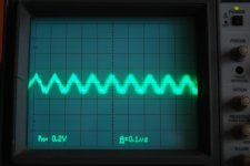
Yes it is a good idea to make a board for it, the number of LED's in the LED-string should be something line 20 for up to 42Volts output. The CroMagnon is, for instance, running at 35Volt and needs 17 LED's in the string.Here is a picture of the output with a 1k cart loading resistor at input. Approx 7-8mV @8MHz (ignore displayed vertical scale).
When the input is loaded with 47ohm oscillating frequency stays the same but amplitude triples.
So far i have not played with PS decoupling of the input stage or mirrors as presumably the layout works with the particular combination of parts some builders have already tried. Why it doesn't work with what i got from the group buy is indeed a mystery.
Has anyone successfully built a Paradise using the GB parts?
Attachments
I am aware of the discussion - it seems to be based on the general discontent of one contributor, rather than any solid fact.
The problem most probably has to do with the particular batches of transistors, or maybe only the Hfe. Hopefully someone will come up with a solution. Shame about the pretty boards, at least those seem to withstand quite a lot of abuse...
Wasn't the initial version scrapped because of oscillations blamed on the output bipolar buffer and hence the fet update? Looks like it wasn't the buffer.
In R1 it was pretty much the entire board oscillating, I was trying to implement a fancty-pantsy-ground layout which basically didnt work. The R2 and R3 (which you have) now have:
1. one BIG ground plane with short connnections
2. SMD footprints on the bottom side of the PCB, right at the mirrors, for local decoupling
3. Much simpler (voltage follower) output stage, which is significantly less prone to oscillation than the R1 output stage
My experience seemed to indicate that high HFE will increase the tendency to oscillate. FWIW, I had transistors at around 400 for NPN and PNP, worked beautifully. My recommendation would be to put 400's in the input stage, and use the decoupling caps in both mirrors (100...1000nF X7R ceramic caps, size 1206 or 1210).
Keep posting if the problem goes away!
- Home
- Source & Line
- Analogue Source
- Paradise Builders