I now had the time to become familiar enough with the Paradise using a Vishay S102K metal foil resistor as a load resistor. So yesterday I finally switched over to a non magnetic Vishay-Dale CMF-55-143, same value.
I didn't really expect to hear a difference, but now it seems I do - the CMF-55-143 sounds leaner, has less volume, overall a bit more contained. I prefer the S102K.
The fact that I hear a difference (or believe to hear a difference) frightens me because of the consequences. The load resistor is not even part of the signal processing, its just a shunt. There are probably dozens, may be hundreds of other resistors in the signal processing later on. Will changing them to S102K yield similar results or is the cartridge load a particularly important resistor?
Regards
Sven
The type of shunt resistor is audible, sadly.
Listen to the sound the groove makes when you drop the needle.
I got this hint from Malkolm Hawksford.
Indeed this is one resistor that matters. Type of resistor can significantly modify sound venue.
Wound resistors tend to sound clearer but somehow more aggressive.
Tantalum gives an overall pleasing tone but sometimes lack "bite"
Carbons (the good ones) are sometimes dull
Best IMO are bulk metal (even trimmers).
The shoemaker has the worst shoes.
Very true....
By the way, nice hat you were wearing at the ETF14!
Hi,
if cost is no object, the BMFs are probabely the most neutral resistors of all.
Your short list misses one of my favourites though, the highly stable NiCr resistors from Susumu.
Considerably cheaper than the BMFs, but otherwise very very close.
jauu
Calvin
Thank you for the tip Calvin... do they make those as trimmers as well ?
I only found those in SMD format
All,
Please have a look at http://www.diyaudio.com/forums/part...r-resistors-small-capacitors.html#post4149279
Frans.
Please have a look at http://www.diyaudio.com/forums/part...r-resistors-small-capacitors.html#post4149279
Frans.
I grew up in such an environment, I suppose it has side-effects.
http://www.diyaudio.com/forums/soli...ds-improvements-stability-14.html#post2348381
(not that I can ever find anything, a fool builds a thousand and too many lockers, but skips a part retrieval system)
http://www.diyaudio.com/forums/soli...ds-improvements-stability-14.html#post2348381
(not that I can ever find anything, a fool builds a thousand and too many lockers, but skips a part retrieval system)
Attachments
All, has someone written down the steps for troubleshooting DC offset at the output, or listed what the most common causes are? I bought a Peak DCS55, pulled all of the BC327/337 from my boards and re-tested all 800-of my transistors, matched to 1% and re-fitted new ones, but still get around 300-400mV DC offset on the output. I have the annotated amplifier schematic and all voltages are very close to those shown.
Hi,
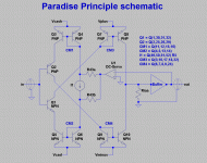
if You look at the schematic of Rev3 (and the simplified principle schematics in the attachment), You´ll see that at DC R9a||R9b (Riaa) form the current path between the upper current mirror (around TP5 and TP6,CM3) and the lower current mirror (around TP 9 and TP10, CM4).
Any imbalance or difference between their currents is routed through R9a||R9b (Riaa).
R9a||R9b equals 36.75kOhms, which means that for every 1µA of current imbalance a offset voltage of 36.75mV results.
Now matching transistors to 1% hfe seems rather sufficient so-so-wise.
Add to this the natural imbalance of NPN to PNP devices, varying Temperature and possibly a slightly detuned Poti R1 (with its own quite high temperature coefficient) and You might rather wonder, that the offset is so small.
The DC-servo is a absolute necessity here to keep things in line.
As the resistors R43a and R43b at the output of the DC-servo are chosen so large in value, the DC-regulation is a bit loose or sloppy.
We learned from an earlier case, that one might reduce the R43s to allow the DC-servo a tighter control.
So as long as the voltages measured at the Testpoints are close to the specced ones, there´s really nothing to worry about.
You may reduce the R43s to 100k or even a bit lower and everything should work out fine.
jauu
Calvin
Attachments
Last edited:
The servo was designed to have as little "authority" as possible. Reducing R43a/b increases the authority. So far, nobody has mentioned any degradation in sound quality (although the increase in authority was very moderate, at least in the cases I remember).
Eliminating the offset is a good thing when your system is DC coupled or has very low crossover frequency down to very low frequencies (single digit hertz). Also, it may improve sound as the RIAA components are no longer exposed to DC, although I am not entirely sure on this argument - I could imagine some impact of DC on the caps, but proof? not sure.....
The offset is typically caused by different current gains in the input stage - ideally , the 8 input transistors (NPN and PNP) should be matched with current gain, base-emitter voltage and also checked for low noise (no "bad apple", so to speak), but thats asking a lot. In all my builds, matching current gain was sufficient.
miepa, this topic is the same for R2 and R3, by the way, there were no changes. I agree fully with Calvin, the DC servo is a must. With it disconnected, the output will be all over the place (in fact, try blowing hot air at the input stage and you'll see the output DC swing a lot, up until the servo catches up.....)
Hello All,
I fnally got a couple of days to progress this project some more.
First, Frans has completely cured the pre-reg oscillations in the both left and right pcbs. All regulated supplies are now quiet. Yeah!
Next, I bridged the supplies on the left pcb, added 10k ohm to the input, 20k ohm to the output, turned it on, and adjusted the input offset to zero. The good news is that "most" of the voltages measure close to what they should.
Now the bad news is that these measurements are way off…
Voutput = 15.2
Vriaa = 15.3
Pin6 of servo chip = -17.7
+side of R5 = -9
-side of R5 = -10
Voltages at Q99: 11.2, -8.3, -9
Everything on this pcb is stock: no Calvin buffer, and no changes from the schematic.
Any clue?
Pierre
Last edited:
Made a mistake above… sorry
Voltages at Q52 (not Q99) C,B,E: 11.2, -8.3, -9
Voltages at Q90 J310 D,G,S: 17.9, 15.3, 16.8 (Vgs is negative)
Voltages at Q99 2SK170 D,G,S: 16.8, 15.4, 15.3 (Vgs is slightly positive)
The right channel measures very close to the left channel pcb.
I tried substituting different J310 in the Q90 position but this made very little change.
Last edited:
- Home
- Source & Line
- Analogue Source
- Paradise Builders


