The board is excellent. As for adjustment of the modulated CCS, i am not at all convinced the modulation is an improvement with normal loads. It will certainly be interesting to test switching the modulation off.
My "tongue in cheek" post related to the optimal resitor values and bias. Probably won't make any difference but i just have to give it a go")
Already raised the bias of the output from 13 to 18mA and cannot hear any difference.
My "tongue in cheek" post related to the optimal resitor values and bias. Probably won't make any difference but i just have to give it a go
Already raised the bias of the output from 13 to 18mA and cannot hear any difference.
Oh, cool. So instead of building it once we can build it twice. Any further radical updates anticipated?
Not-lol.... Lol.
It will depend very much on how much capacitance is mixed in with your nominal load and how much interference is picked up and transmitted with the signal to be attenuated at the next RF filter............Already raised the bias of the output from 13 to 18mA and cannot hear any difference.
If you have low capacitance and low interference, then you will not be able to measure the effect of the unused excess current capability.
A big thanks to all for there advice I am now in a hum free Paradise.
Cool... that is the way it should be
A big thanks to all for there advice I am now in a hum free Paradise.
Enjoy it

Not quite Paradise yet....
Finally got around to putting my Paradise boards (boards and parts from the original GB plus BC327/BC337 that I sourced for matching) together and I have a few issues. I'm using the 'official' pre-regulator boards to power and these were built up first. These produce around +/-43.8V with no load which seems about right. I hadn't measured the rails for noise until now but we'll come back to that later...
I built up the Paradise boards using bi-polars that matched to 1% or better across the board (all measured at hFE 492 +/-2). The input trannies were the very best matches although I don't think the accuracy of my meter (Peak DCA55) is better than about 2%. On power up of just the regulator sections it all looked good, all LEDs shining and, after trimming, a nice stable +/-18.2V on both boards. A good start.
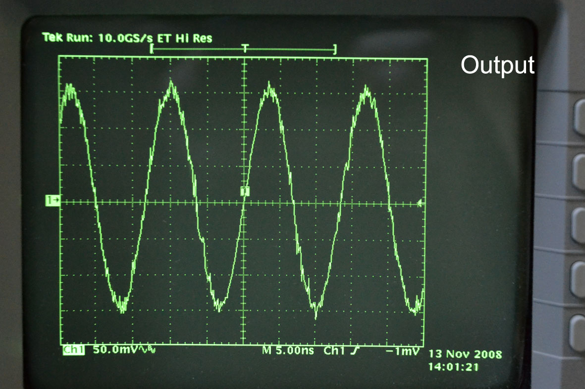
I inserted the bridges to power the amplifier and did a little initial trimming of the input offsets then left to run for a few days to let any necessary cap forming happen. I then added a 47R resistor across the input and re-trimmed for 0mV, both channels seem very stable in this respect. I then checked the output for DC and found an offset wandering from roughly +100mV to -100mV but I also found about 14V of AC voltage! At that point I had no RIAA caps so added these and the AC on the output (as far as my Fluke 179 reads) was gone. Clearly though that level of AC on the output was not right so I got the scope out and found that both channel had an output of around 150mV RMS at about 73 to 77MHz. For good measure there's also some much higher frequency components in the output, up in the low GHz region albeit at a lower level.
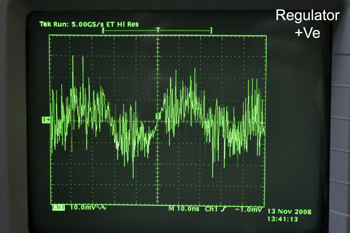
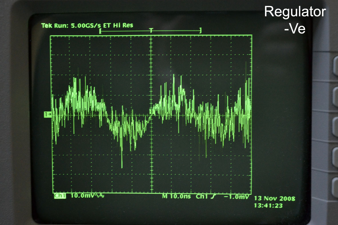
I decided to focus on one channel to start with and did the following. Checked the power rails after the regulator, these looked very noisy with around 50mV of crap in the high MHz region. I added the compensating caps to the regulator section and this improved matters a little but the noise remains. I measured the voltages around the board and they're all very close to what they should be. The only 'imbalance' being +.6V -.54V either side of the 82R resistor, R5. Where I do have an 'issue' is the output from the servo as this floats from around +5V to +8V which seems high although not entirely out of spec.
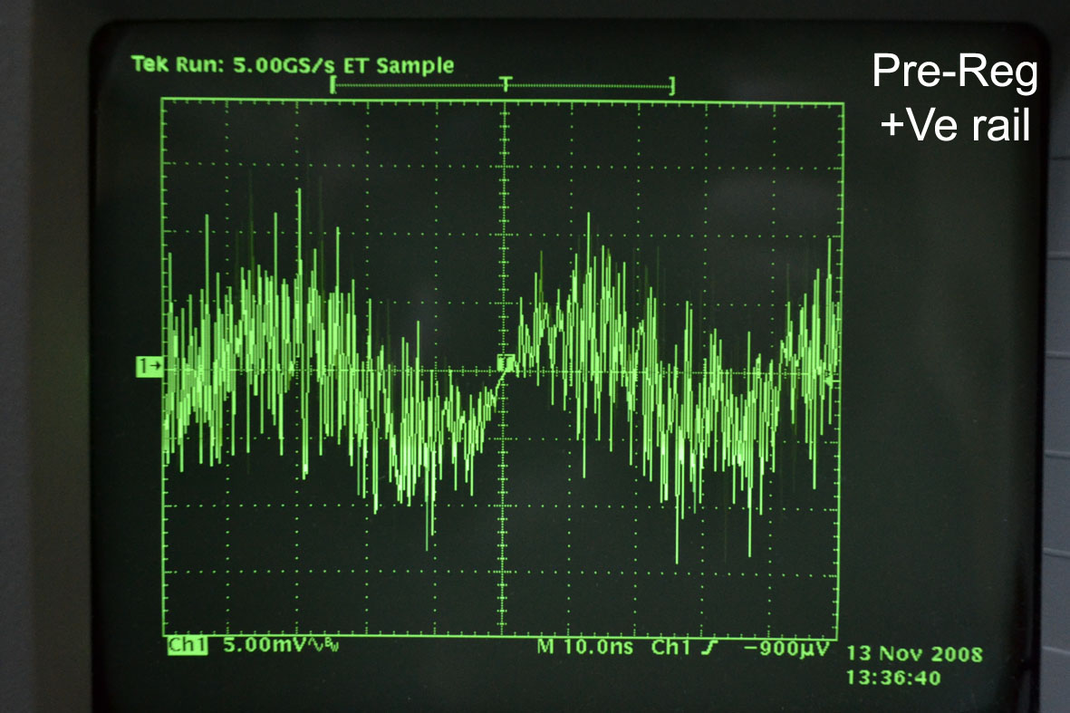
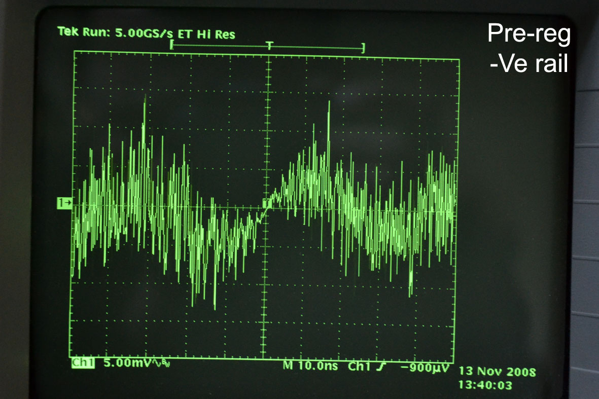
I put the scope on the output from the pre-regulator and, perhaps unsurprisingly, there's noise present. Now I'm not saying I expected to see perfect DC but surely there shouldn't be much noise after the pre-regulator has done its job. There’s an even higher level of noise on the power rails coming out of the regulator, ground is also similarly noisy when measured at the regulator-amplifier bridge.
Here are shots of the ‘scope screen:
Finally got around to putting my Paradise boards (boards and parts from the original GB plus BC327/BC337 that I sourced for matching) together and I have a few issues. I'm using the 'official' pre-regulator boards to power and these were built up first. These produce around +/-43.8V with no load which seems about right. I hadn't measured the rails for noise until now but we'll come back to that later...
I built up the Paradise boards using bi-polars that matched to 1% or better across the board (all measured at hFE 492 +/-2). The input trannies were the very best matches although I don't think the accuracy of my meter (Peak DCA55) is better than about 2%. On power up of just the regulator sections it all looked good, all LEDs shining and, after trimming, a nice stable +/-18.2V on both boards. A good start.
I inserted the bridges to power the amplifier and did a little initial trimming of the input offsets then left to run for a few days to let any necessary cap forming happen. I then added a 47R resistor across the input and re-trimmed for 0mV, both channels seem very stable in this respect. I then checked the output for DC and found an offset wandering from roughly +100mV to -100mV but I also found about 14V of AC voltage! At that point I had no RIAA caps so added these and the AC on the output (as far as my Fluke 179 reads) was gone. Clearly though that level of AC on the output was not right so I got the scope out and found that both channel had an output of around 150mV RMS at about 73 to 77MHz. For good measure there's also some much higher frequency components in the output, up in the low GHz region albeit at a lower level.
I decided to focus on one channel to start with and did the following. Checked the power rails after the regulator, these looked very noisy with around 50mV of crap in the high MHz region. I added the compensating caps to the regulator section and this improved matters a little but the noise remains. I measured the voltages around the board and they're all very close to what they should be. The only 'imbalance' being +.6V -.54V either side of the 82R resistor, R5. Where I do have an 'issue' is the output from the servo as this floats from around +5V to +8V which seems high although not entirely out of spec.
I put the scope on the output from the pre-regulator and, perhaps unsurprisingly, there's noise present. Now I'm not saying I expected to see perfect DC but surely there shouldn't be much noise after the pre-regulator has done its job. There’s an even higher level of noise on the power rails coming out of the regulator, ground is also similarly noisy when measured at the regulator-amplifier bridge.
Here are shots of the ‘scope screen:
At that point I had no RIAA caps so added these and the AC on the output (as far as my Fluke 179 reads) was gone. Clearly though that level of AC on the output was not right so I got the scope out and found that both channel had an output of around 150mV RMS at about 73 to 77MHz. For good measure there's also some much higher frequency components in the output, up in the low GHz region albeit at a lower level.
The "wandering" of +/-100mV is quite normal and due to the thermal variations of the input stage. Others have reported that when they put a shield or heatsink there this stuff is gone. The high frequency stuff you are seeing is the amplifier oscillating, not the power supply (that would be a couple MHz).
I decided to focus on one channel to start with and did the following. Checked the power rails after the regulator, these looked very noisy with around 50mV of crap in the high MHz region. I added the compensating caps to the regulator section and this improved matters a little but the noise remains. I measured the voltages around the board and they're all very close to what they should be. The only 'imbalance' being +.6V -.54V either side of the 82R resistor, R5. Where I do have an 'issue' is the output from the servo as this floats from around +5V to +8V which seems high although not entirely out of spec.
I put the scope on the output from the pre-regulator and, perhaps unsurprisingly, there's noise present. Now I'm not saying I expected to see perfect DC but surely there shouldn't be much noise after the pre-regulator has done its job. There’s an even higher level of noise on the power rails coming out of the regulator, ground is also similarly noisy when measured at the regulator-amplifier bridge.
The servo output variation is due to whats described above, not unusual. Check the assembly guide, there is some information on the compensation caps for the amplifier as well. BTW, did you put the SMD caps on the bottom side of the PCB?
If that fixes it, this will be the second confirmed case of Paradise amplifiers oscillating, not too bad I think.....
The "wandering" of +/-100mV is quite normal and due to the thermal variations of the input stage. Others have reported that when they put a shield or heatsink there this stuff is gone. The high frequency stuff you are seeing is the amplifier oscillating, not the power supply (that would be a couple MHz).
The servo output variation is due to whats described above, not unusual. Check the assembly guide, there is some information on the compensation caps for the amplifier as well. BTW, did you put the SMD caps on the bottom side of the PCB?
I'm not too worried about this, as you say it's quite normal and the boards are in free air currently. Yes, I have fitted the SMD caps.
If that fixes it, this will be the second confirmed case of Paradise amplifiers oscillating, not too bad I think.....
Well, I suppose that depends on your perspective
After all the transistor matching and careful stuffing it's pretty depressing from where I'm sitting. I'm going to take a break from it for now, I'll have a hunt for some suitable compensation caps and try that later in the week. I'm wondering how many working Paradise builds are out there now, it seems odd that I've run into the same issue that analog_sa had all those months ago. I find it really frustrating when there's no obvious reason for something like this, it all feels a little too 'random' and that makes no sense to me. That said I'm very appreciative of all the design efforts that went into this and for any help given.
Paulski, I've built 6 now, mixture of r2 and r3 pcbs. I've never had an issue apart from one oscillating shunt that wasn't sloppy soldering. The last set i built were all matched to better than 1% (everywhere).
I've never used anything over 460hfe and always matched to better than 1% in each position always using matches in the 400-420hfe in the input stage.
I've never used anything over 460hfe and always matched to better than 1% in each position always using matches in the 400-420hfe in the input stage.
Managed to find time to bung a couple of cheapo 33pF ceramics on the board and decided to skip the 'scope and just go straight to listening to the output. Yes, I'm impatient! With a old (missing half its cantilever) Linn Arkiv connected to the input we've definitely got a working amplifier. There's a little hum (not surprising as it's not cased or properly grounded) but very little noise. Will put the 'scope on it tonight and see if the oscillation is gone, fingers crossed! I've also got to replace the J109s and resistors in the PSU but will do that once it's stable.
By the way Simon, how did you measure the gain so accurately?
By the way Simon, how did you measure the gain so accurately?
Managed to find time to bung a couple of cheapo 33pF ceramics on the board and decided to skip the 'scope and just go straight to listening to the output. Yes, I'm impatient! With a old (missing half its cantilever) Linn Arkiv connected to the input we've definitely got a working amplifier. There's a little hum (not surprising as it's not cased or properly grounded) but very little noise. Will put the 'scope on it tonight and see if the oscillation is gone, fingers crossed! I've also got to replace the J109s and resistors in the PSU but will do that once it's stable.
By the way Simon, how did you measure the gain so accurately?
If I remember well, the oscillation's on analog_sa's preamp stopped after replacing the BC's in the power supply. I'm sorry to say that I have no explanation why it fixed the problem. Maybe analog_sa's can add to this comment. One thing of concern was that very high Hfe BC's in the PSU may be a factor of concern, the PSU does not need BC's with very high Hfe's (I think it was said that BC's from the 25-groep may be preferable). I myself am currently using MPSA42/92 in the PSU versions that I build.
Last edited:
Managed to find time to bung a couple of cheapo 33pF ceramics on the board and decided to skip the 'scope and just go straight to listening to the output. Yes, I'm impatient! With a old (missing half its cantilever) Linn Arkiv connected to the input we've definitely got a working amplifier. There's a little hum (not surprising as it's not cased or properly grounded) but very little noise. Will put the 'scope on it tonight and see if the oscillation is gone, fingers crossed! I've also got to replace the J109s and resistors in the PSU but will do that once it's stable.
By the way Simon, how did you measure the gain so accurately?
The recommended jfet for the PSU is the J113 (this has been discussed many times
). See also: http://www.diyaudio.com/forums/analogue-source/218625-paradise-builders-213.html#post3473388 (post #2127)These are the most important/relevant messages regarding PSU and Pre-Reg.
- Mpp #4375 PSU-pre-regulator.
- Mpp #4610 V2 Schemas UPS and Amp.
- Mpp #6506 CCS fine-tuning.
- Mpp #6462 PSU with my notes.
- Mpp #6809 Do not try to feed the CVS of the CCS of the shunt with a regulated power supply.
- Mpp #7127 More about transformer selection.
- Mpp #7635 Single and dual transformer wiring (also corrected drawing) (See also #7733).
- Mpp #7733 Grounding (PSU, RIAA and Player).
- Mpp #7810 35V PSU for the CroMagnon.
- Mpp #7830 The PSU explained.
- Mpp #8386 My resistor recommendation’s.
- My Paradise #56 PSU Noise.
- Masterpiece #951 That's not a PSRR test (it's a CIR test)
- PradiseBuilders #13 Schema's and assembly guide.
- PradiseBuilders #155 Vdc input voltage minimum simulated.
- PradiseBuilders #970 PSU oscillates; posible solutions?
- PradiseBuilders #983 Compensating the PSU for oscillations.
- PradiseBuilders #1173 Fixing oscillations (up to #1182).
- PradiseBuilders #1322 Fuse .
- PradiseBuilders #1387 Updated Paradise R3 assembly guide (Also German).
- PradiseBuilders #1403 Capacitors bad vs good.
- PradiseBuilders #1593 PSU Power Transistor selection.
- PradiseBuilders #1644 PSU Output Impedance.
- PradiseBuilders #1680 PSU Power Supply Suppression Ratio(PSSR).
- PradiseBuilders #1772 NJF selection for the PSU.
- PradiseBuilders #1887 Empirical NJF Rgs determination.
- PradiseBuilders #2127 More about the PSU fets (J113's etc).
- PradiseBuilders #2969 About the Paradise PSU using Calvin buffers.
If I remember well, the oscillation's on analog_sa's preamp stopped after replacing the BC's in the power supply. I'm sorry to say that I have no explanation why it fixed the problem. Maybe analog_sa's can add to this comment. One thing of concern was that very high Hfe BC's in the PSU may be a factor of concern, the PSU does not need BC's with very high Hfe's (I think it was said that BC's from the 25-groep may be preferable). I myself am currently using MPSA42/92 in the PSU versions that I build.
To be clear are you saying that changing out the BCs in the PSU fixed oscillation in the amplifier? I'm happy to do it although I don't much fancy removing the heat sink to get at the ones underneath
I realised the J113s were the preferred devices a while back but didn't have them to hand as I only had what came with the BG. I've got them now so will fit tonight with the 1K resistors.
After re-reading the last few posts I see that it is the amplifier oscillating (not the PSU) so, it is not needed to swap the PSU BC's (sorry for the confusion).
After re-reading the last few posts I see that it is the amplifier oscillating (not the PSU) so, it is not needed to swap the PSU BC's (sorry for the confusion).
No apology necessary, I think it's my fault for confusing the issue by posting the 'scope traces from the PSU rails which was just noise and not oscillation. Anyway I'm relieved that I can leave that heat sink where it is
.Hopefully in a couple of days I'll get round to sorting out the case for the Paradise boards to nestle in and see how they sound once they're properly shielded and grounded.
Hi Guys, i am in process of installing of calvin buffer into Paradise 3. Just a question regard connecting the output of the buffer to 5R resistor- which end of the 5R do i connect to ?. I am not sure if it's on the output side then i can just connect directly to rca output or does the buffer need to be terminate in series with 5R resistor.
Quan
Quan
- Home
- Source & Line
- Analogue Source
- Paradise Builders