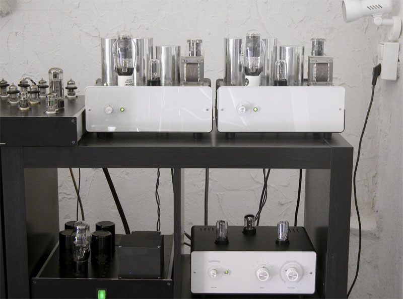
So, here it is now. I kind of liked this industrial design of the steel cases so I got 2 small ones instead of one big. Hum is almost gone, just a little bit audible hum that is not significantly louder than the noise floor. I have to turn the volume up much further than I could while listening to music, I can live with that.
It sounds still very good which means I likely didn't ruin something during my case experiments... surprise
Regards
Sven
Hi Sven, great, your build looks amazing! Any first sound impression?
Hi Alfred, from the 30 minutes I just listened it doesn't sound different than the temporary setup I described earlier (very good!). More than 30 minutes is not possible with weather like this, my 2 F4s are not really compatiblel with the 30 degrees in my attic ") .
.
.
Last edited:
Its not available in another color, anyway
Its looks OK "stand alone", however it doesn't really fit the rest of the stuff. I consider powder coating it black...
Conrad does have those in black. But I like the grey much better.
Heinz
So, here it is now. I kind of liked this industrial design of the steel cases so I got 2 small ones instead of one big. Hum is almost gone, just a little bit audible hum that is not significantly louder than the noise floor. I have to turn the volume up much further than I could while listening to music, I can live with that.
An externally hosted image should be here but it was not working when we last tested it.
It sounds still very good which means I likely didn't ruin something during my case experiments... surprise
Regards
Sven
Just 'wunderbare'
https://www.youtube.com/watch?feature=player_detailpage&v=ck6AZfJbSd4Sven, yes I am:
They are not made by Hammond though:
Metall-, Aluminium-Gehäuse - im Conrad Online Shop günstig kaufen
They are not made by Hammond though:
Metall-, Aluminium-Gehäuse - im Conrad Online Shop günstig kaufen
Yes, there are other types but I couldn't find anything with the right size. Nice picture, we have something in common - I'm a bottle collector, too.
So, here it is now. I kind of liked this industrial design of the steel cases so I got 2 small ones instead of one big. Hum is almost gone, just a little bit audible hum that is not significantly louder than the noise case experiments... surprise
Regards
Sven
Steel or aluminium case,that is the question?
Hi SvenSo, here it is now. I kind of liked this industrial design of the steel cases so I got 2 small ones instead of one big. Hum is almost gone, just a little bit audible hum that is not significantly louder than the noise floor. I have to turn the volume up much further than I could while listening to music, I can live with that.
An externally hosted image should be here but it was not working when we last tested it.
An externally hosted image should be here but it was not working when we last tested it.
An externally hosted image should be here but it was not working when we last tested it.
It sounds still very good which means I likely didn't ruin something during my case experiments... surprise
Regards
Sven
Splendid lettering... where did you have it done ?
Kamis: the U shaped parts are steel but I decided to get not too exited about it. One day I will try whether I hear a difference...
Ricardo: the company is pretty well known among the German DIY community - Schaeffer. They have a nice simple CAD program everybody can use to create and order parts. Not exactly cheap but live is too short for crappy faceplates.
Sven
Ricardo: the company is pretty well known among the German DIY community - Schaeffer. They have a nice simple CAD program everybody can use to create and order parts. Not exactly cheap but live is too short for crappy faceplates.
Sven
calvin buffer for paradise
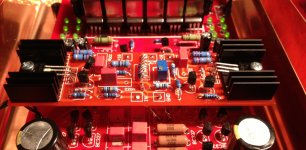
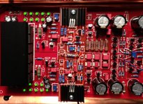
Here the first pictures of the Calvin buffer PCB. It is designed so it fits nicely on top of the main PCB.
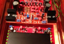
The "front" picture shows how its connected to the "RIAA EXT" connector. The "shunt" picture shows the power supply connections. The output of the buffer needs to be connected to the 4.7Ohm resistor on the main board, since it is this output that the servo uses to control the DC balance. On the main board, a few components from the output buffer need to be removed so that this buffer here works. Mechanical mounting is easy, below the heatsinks threaded bolts (M3 x 15mm) can be glued to the main board, and the screws that press the transistors to the heatsink will then also fix the board. I will put more details in the assembly guide, one day
Schematic is attached as well, this does not have the original parts but some substitutes, in order to make it easier to assemble. The output bipolars are 2SC1381 plus a little heatsink, considering the supply voltage is higher than in the original design from Calvin, and so is the power dissipation (plus, the shunt regs are increasing the ambient temperature so I went on the safe side ).
Adjustment is easy, just put a DMM between input and output and adjust the trimpot until this shows 0V. First sound impressions from yesterday night were great. My theory is that with an output buffer with zero offset, the signal voltage across the RIAA components is symmetric around 0V as well, whereas with buffer offset this voltage will have a DC bias, and that may cause a different sound. But I will ask this question over at the MPP thread...
hope you like it!
Here the first pictures of the Calvin buffer PCB. It is designed so it fits nicely on top of the main PCB.
The "front" picture shows how its connected to the "RIAA EXT" connector. The "shunt" picture shows the power supply connections. The output of the buffer needs to be connected to the 4.7Ohm resistor on the main board, since it is this output that the servo uses to control the DC balance. On the main board, a few components from the output buffer need to be removed so that this buffer here works. Mechanical mounting is easy, below the heatsinks threaded bolts (M3 x 15mm) can be glued to the main board, and the screws that press the transistors to the heatsink will then also fix the board. I will put more details in the assembly guide, one day
Schematic is attached as well, this does not have the original parts but some substitutes, in order to make it easier to assemble. The output bipolars are 2SC1381 plus a little heatsink, considering the supply voltage is higher than in the original design from Calvin, and so is the power dissipation (plus, the shunt regs are increasing the ambient temperature so I went on the safe side ).
Adjustment is easy, just put a DMM between input and output and adjust the trimpot until this shows 0V. First sound impressions from yesterday night were great. My theory is that with an output buffer with zero offset, the signal voltage across the RIAA components is symmetric around 0V as well, whereas with buffer offset this voltage will have a DC bias, and that may cause a different sound. But I will ask this question over at the MPP thread...
hope you like it!
Attachments
- Home
- Source & Line
- Analogue Source
- Paradise Builders