spec was for the SMT caps under the board
I consult my (old) material bill.
C901 / C902 / C903 ... = 1microF CER (footprint 1206)
I hope this help.
Allez, salukes.
Karel
I consult my (old) material bill.
C901 / C902 / C903 ... = 1microF CER (footprint 1206)
I hope this help.
Allez, salukes.
Karel
correct, many thanks
When you reduce the emitter resistors you raise the gain and lower the current feedback.
Safe ? I do not think that is the right word. You can try 10 Ohm. That should reduce the Johnson noise by ca. 3dB.
Thanks for the answer! I realize that this move can be beneficial for lower output MC's (0,1-0,2 mV nominal) and can be a future enhancement and also a one-off (those transistors are extinct and/or cost a fortune). With a hFE of around 315, they are also a lower gain set, compared to what I could select from within the BC337/327 (580). I really start to be unsure if this move is worthy of all the work.
For now I am busy to finalize a quality preamplifier with relay based volume control, so that I can really have something up to Paradise performance. CX 1000 has too much gain (I normally listen with volume control at 9 o clock and the ground shaking levels are with the same knob at 12 o'clock). Still no hiss at those positions (only with ears near the speakers) and that is a huge technical advantage compared to the original integrated in Yamaha.
Next, I am waiting for VSSA modules to come, so still a bit more extra work till the second set of Paradise boards.
Back on topic, I left the Paradise boxes running continuously and the sound is improved still a bit. I had a slight hum with the volume set to the maximum position (that's too huge gain, anyway) and that is also gone after few days. So indeed the capacitors forming is taking around 3-5 days of continuous run.

I am going to build Paradise phono in the future when I finish my projects I started a long time ago. I have even bought 200 pieces of both transistors types at my local electronic parts shop, they are so widespread and cheap.
70 percent of both polarity are with hfe between 440 to 460. Is it good matching for the input stage(Hesener recommends 400hfe)?
After trial experience, I wish to know if Paradise is offset free, stable and long time reliable design.
Regarding subjective listening tests, I think that Paradise should be compared with existing phono stages only with the same or similar raw and regulated power supply to be reliable. Power supply differences are very important for final results.
Mine is definitely rock stable with an offset between +/- 3mV and I used transistors with hFE of 568. I think when using high hFE transistors in the input stage it is mandatory to use thermal coupling. Especially when the hFE is over 500, I noticed the fluctuation with temperature is huge (even holding them with the fingers for few seconds and you are 25 or even 30 extra added to the real hFE).
I have built a special fixture for matching, with a ZIF 24 pins socket where I put 8 transistors at a time. The ZIF is terminated with 8 female headers of three pins each. The cable from Atlas (or any other convenient transistor tester) is terminated with a male 3 pin header that I can easily move from one transistor to another without touching the transistors. I leave the transistors about one minute under a blow of a 12 cm fan to thermally stabilize and then measure the set of 8.
The exact value is not very important, as different meters all gave me different values for hFE. What is important is to have all transistors in a matched set measured at exactly the same temperature and with the same device, and this is especially important for high hFE ones. Now you can imagine why it took me more then 2 months to sort 6000 transistors.
There is local feedback of course, and matching very close is therefore not mandatory according to what I read in this thread. I just did not want to take any chance") But reading some experiences I assume that using huge hFE input without thermally coupling and isolating them from air movements MIGHT drive you into problems (not mandatory, depending on how the enclosure box is built and how the position of the PCBs is in the box, and maybe lots of other factors).
But reading some experiences I assume that using huge hFE input without thermally coupling and isolating them from air movements MIGHT drive you into problems (not mandatory, depending on how the enclosure box is built and how the position of the PCBs is in the box, and maybe lots of other factors).
I have built only two channels of course, that is why I can only comment on the hFE factor from my own experience. If you follow the excellent guide and measure every component before soldering it can work from the first power up. If nothing smokes, I assume it will stay like that for years.
I have built a special fixture for matching, with a ZIF 24 pins socket where I put 8 transistors at a time. The ZIF is terminated with 8 female headers of three pins each. The cable from Atlas (or any other convenient transistor tester) is terminated with a male 3 pin header that I can easily move from one transistor to another without touching the transistors. I leave the transistors about one minute under a blow of a 12 cm fan to thermally stabilize and then measure the set of 8.
The exact value is not very important, as different meters all gave me different values for hFE. What is important is to have all transistors in a matched set measured at exactly the same temperature and with the same device, and this is especially important for high hFE ones. Now you can imagine why it took me more then 2 months to sort 6000 transistors.
There is local feedback of course, and matching very close is therefore not mandatory according to what I read in this thread. I just did not want to take any chance
But reading some experiences I assume that using huge hFE input without thermally coupling and isolating them from air movements MIGHT drive you into problems (not mandatory, depending on how the enclosure box is built and how the position of the PCBs is in the box, and maybe lots of other factors). I have built only two channels of course, that is why I can only comment on the hFE factor from my own experience. If you follow the excellent guide and measure every component before soldering it can work from the first power up. If nothing smokes, I assume it will stay like that for years.
Hi there.
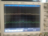
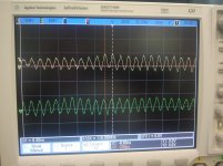
Finally I got the time to power up my paradise and do some measurements at our physics laboratory.
The pictures show the supply voltages (+/- 18V)without and within the caps for the distortion treatment.
the signal can be influenced by turning or tilting the pcb.
Though I think the signals are influenced by the enviroment. -No problem with the paradise.
Does anyone agree?
The supply is a simple one with only one Transformer.
Attachments
 )
)- Home
- Source & Line
- Analogue Source
- Paradise Builders