All parts for final power supply have been ordered, it is essentially the supply shown in this thread, but I have decided to build one for each channel, but sharing raw filtered DC and filtered screen supply. I will probably also use 6BD5GT as pass tubes and DC filament power on the cascode error amplifiers in the supply.
I'll post some details on the supply build as I proceed
I'll post some details on the supply build as I proceed
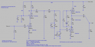
Here are some minor variations on the theme previously expressed. Essentially the changes are two fold (and not implemented in my design), the first eliminates the dependence on grid current for biasing the upper half of the cascode, and the second (previously shown) removes the battery in the choke based mu-follower from the signal path.
As always there are trade-offs, the quality of the power supply becomes even more critical with the fixed bias version of the cascode in exchange for hopefully more consistent behavior over the life of the tubes, and in the case of the mu-follower the quality of the coupling capacitor may impact sound quality. Both add additional complexity, although relatively minimal cost. Just an alternative to experiment with if so inclined.
As always there are trade-offs, the quality of the power supply becomes even more critical with the fixed bias version of the cascode in exchange for hopefully more consistent behavior over the life of the tubes, and in the case of the mu-follower the quality of the coupling capacitor may impact sound quality. Both add additional complexity, although relatively minimal cost. Just an alternative to experiment with if so inclined.
Attachments
Some comments on parts
All resistors in this design in both the supply and pre-amp circuitry are metal film.
Pre-Amp:
I've older Holco H4 in most locations in the audio path, but the cascode plate load resistor is a 2W Roederstein 10K 1%, and series resistor in the EQ is a Caddock MK-132. Nothing terribly exotic or expensive here.
The EQ caps are selected, closely matched REL RT polystyrene and foil type with a base tolerance of 5% - quite cheap actually.
The most expensive parts are the coupling caps which are TRT Dynamicaps, but the Russian FT-3 should work well for the 0.22uF. (Leave plenty of room)
The 6S3P seems quite a bit more forgiving wrt to VHF oscillations than the 5842 or D3A or any number of other high transconductance tubes, no signs of any oscillation using my 100MHz Tek scope. Probably not a good idea to omit the grid stopper on the input however, both for stability and potential RFI.
Power Supply:
I'm stacking Panasonic 450V caps in the current supply to achieve 50uF @ 900V. Each of these caps has a resistor across it to assure that voltage divides equally across each cap.
The output cap is film.. There is no reason why all the HV supply caps could not be film if cost is not a concern.
Power transformer: Edcor XPWR-228-120
Choke: Edcor CXC100-5H-200mA
Filament: Antek AN-0509
Note that in theory at least an EI transformer for the filament supply should provide more isolation to EMI on the power line - in practice in a half dozen or so designs where I have used these toroids there has been no problem.
Having heard your previous designs and this new design, I have to say that this latest "Muscovite" is substantially better. And this was with the temporary power supply.
What chokes did you source for the phono preamp? I think that the Magnequest EXO-01 were the only ones I found that had the DCR you specified and oddly enough, some makers do not list DCR in their specifications.
What chokes did you source for the phono preamp? I think that the Magnequest EXO-01 were the only ones I found that had the DCR you specified and oddly enough, some makers do not list DCR in their specifications.
Last edited:
Here is the first cut of the BOM. I will add the power supplies sometime over the next few hours to days, and update here. Just download the latest version when available - will not change the existing BOM. Note that I have listed recommended parts, do not feel bound by my recommendations, although you may end up with something that sounds a bit different as a result.
Edit: Updated bom with high voltage power supply added 2012-06-09
Edit2: Updated bom with filament supply added 2012-06-10
Edit: Updated bom with high voltage power supply added 2012-06-09
Edit2: Updated bom with filament supply added 2012-06-10
Attachments
Last edited:
Excellent. Thank you Kevinkr. It's even in spreadsheet form! I hope to get to this over the summer, which for me begins in a few weeks as the kids get out of school. I'll probably start off with a parts bin breadboard version and modify from there, though I'll no doubt use the Edcor x-formers from the start. I saw no listing for the power xformer but put in an inquiry about it. Others are quite reasonably priced, even for a die-hard miser like me.
Carl
Carl
Last edited:
I've updated the BOM and replaced the original with the revised BOM, note that the difference is the addition of a second page covering the high voltage supply. I've yet to add the filament supply.
Note with regard to the high voltage supply there is no reason if desired not to go with independent regulators for each channel - that is exactly what I am doing for mine. Only one power transformer, and choke are required - the input filter caps C1, C3, and C4 do not change. Just double quantities for all other parts.
Don't forget sockets for the PSU as I forgot to include them in this cut of the BOM.
Acceptable pass tubes for use in this supply design include the 5881, 6L6, 6BQ5, and 6BD5GT - note the different pin outs where applicable.
Added the detail for the filament regulator to the BOM. Note that in addition to the LT1084 5A regulator you will need a silpad, suitable insulated hardware and if not using the PSU chassis as a heat sink, some sort of suitable heatsink..
Dissipation in the regulator could be 12W or more depending on line voltage and transformer selected. Use a heatsink with thermal resistance to ambient of less than 2C/W.
Note that the filament supply wants to sit fairly close to ground so as not to overstress the 6S3P filament insulation so this really precludes using this filament supply to power the 12AX7A in the high voltage regulator because of the near 200V differential between filament and cathode.
Note also that with regards to "C4" in the high voltage regulator this could be changed to 110uF total using a pair of 220uF/350 - 450V caps in series shunted with 220K 1W resistors to assure that the voltage divides equally between them. This would be good for a few dB additional ripple reduction.
Listening to this thing every day, digital now on the back burner.. I'm quite pleased with the overall performance.
Lest there be any confusion this design was intended for use with a wide range of cartridges, LOMC types like my SPU should be used with a step-up transformer to maintain good SNR despite the high gain. (I've been asked about this a few times.)
While I obviously can't review my own design I can describe a few of its sonic attributes. Perhaps this will help a few people to decide whether this is the sort of sound they would be interested in.
I would describe it as fast, detailed, with very good imaging, and has very extended frequency response. Very open sounding. It is also quiet, and very clean..
Compared to my last design it has much less character which I take as a good thing, the previous design tended to be a bit warm and euphonic sounding, and lacked both the detail and imaging of this design. (It was quite decent.)
I aim for neutral, and whether or not it actually is, I believe it comes about as close as I know how at this point in time. For the objective as I've mentioned it also measures well.
While I obviously can't review my own design I can describe a few of its sonic attributes. Perhaps this will help a few people to decide whether this is the sort of sound they would be interested in.
Any chance of a needledrop thru this phono stage?
Compared to my last design it has much less character which I take as a good thing, the previous design tended to be a bit warm and euphonic sounding, and lacked both the detail and imaging of this design. (It was quite decent.)
12AX7's?
jeff
Hi Jeff,
Not currently set up to do digital captures, but perhaps at some point in the future.
The previous design was based on D3A triode connected front end, and a 5842 output stage, both stages with gyrator loading - the gyrators being implemented with 5687 dual triodes. The main issue with this older design is the high input capacitance. Both designs use passive EQ and quiet tube regulated supplies.
Try the D3a as a pentode in the front end. Lower input C and IMHO, deals with the criticism you have of the sound.
Yes, my exact thought and this is in the cards - essentially a new design though as the current design is built around the characteristics of its triode front end and gyrator loading.
Well the chassis for the power supply arrived the other day, so now all I am waiting for are the transformer and choke from Edcor.
I think I failed to take my own advice and was looking at my new supply chassis last night and realized that it is going to take some very careful planning to get everything to fit.
I'll post a picture at some point of the chassis and the ensuing build. You'll want to avoid my mistake..
I think I failed to take my own advice and was looking at my new supply chassis last night and realized that it is going to take some very careful planning to get everything to fit.
I'll post a picture at some point of the chassis and the ensuing build. You'll want to avoid my mistake..
Why is it that no matter how many things we build, trying to get the power supply to fit is something that occurs time and time again
It's particularly embarrassing as I always warn against building in too small a box, and I appear somehow to have not taken my own advice.
What's even funnier is that I made this box somewhat larger than the one destined to contain the supply for my next 26 dht line stage which has an additional filament supply this one does not. What to do..
- Home
- Source & Line
- Analogue Source
- The "Muscovite" 6S3P Tube Phonostage