This project got started for no other reason than I needed another phono stage to use with my second turntable. I named it the Muscovite simply because it uses the Russian 6S3P-EV high frequency triode.
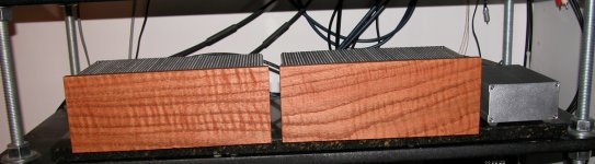
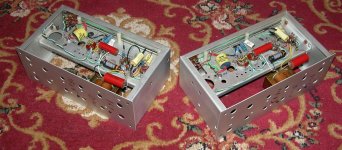
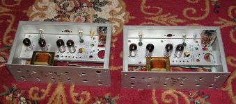
The design is built on a couple of repurposed Tektronix vacuum tube pulse generator chassis.
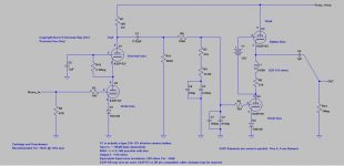
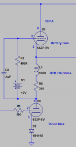
I thought I would have some fun with this design so it literally includes everything but the kitchen sink. The input stage is what I would term a mixed bias cascode with diode and grid leak bias. The second stage is a choke perverted version of the mu-follower which uses a combination of battery and diode bias.
It was also intended to be cheap and use parts I have in my stash.. (mostly)
The design has minimal PSRR and must run from a very quiet power supply - in my case tube preferred, but I suspect the Salas HV shunt regulator could be a good choice.
The gain is deliberately insanely high (>54dB) as I use a line stage with 4dB of voltage gain, and I wanted CD reference level output. It also had to be quiet.
Some technical information:
Gain: ~56dB
RIAA: +/- 0.1dB with trim and selected parts.
Input capacitance: Low, in theory 30pF is possible, with care 50pF or less is achievable.
Edit 2013-05-12: Please see later posts in thread for current HV supply and audio circuit designs.
The design is built on a couple of repurposed Tektronix vacuum tube pulse generator chassis.
I thought I would have some fun with this design so it literally includes everything but the kitchen sink. The input stage is what I would term a mixed bias cascode with diode and grid leak bias. The second stage is a choke perverted version of the mu-follower which uses a combination of battery and diode bias.
It was also intended to be cheap and use parts I have in my stash.. (mostly)
The design has minimal PSRR and must run from a very quiet power supply - in my case tube preferred, but I suspect the Salas HV shunt regulator could be a good choice.
The gain is deliberately insanely high (>54dB) as I use a line stage with 4dB of voltage gain, and I wanted CD reference level output. It also had to be quiet.
Some technical information:
Gain: ~56dB
RIAA: +/- 0.1dB with trim and selected parts.
Input capacitance: Low, in theory 30pF is possible, with care 50pF or less is achievable.
Edit 2013-05-12: Please see later posts in thread for current HV supply and audio circuit designs.
Attachments
I am now using this with my TD-124/II/Schick/SPU set up and much prefer it to the one it unintentionally has replaced.
There are a couple of variants to the circuitry that I have not explored, but will share here for those who are interested.
I have included an alternative biasing arrangement for the mu-follower upper triode for those concerned about possible battery induced audio colorations. In practice I have not had a problem with this issue and was not looking to spend too much on this design so it's economical. No detectable downside so far.
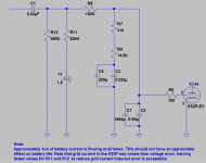
I have also included a way to apply battery bias to the lower tube in the mu follower. This would eliminate potential distortion in the mu-follower due to modulation of the 1N4148 dynamic impedance due to variations in the audio signal current. Again I have not heard or measured a problem with this, and have not tried this approach and probably won't.
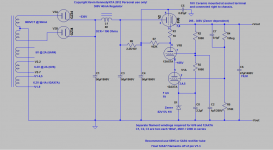
Note that there will be an Edcor plate supply transformer as I have ordered a custom for mine.
The filament transformer is an Antek AS/AN-0509.
With care this ought to be possible to duplicate for $300 or less with careful parts shopping. Mine cost a bit more than this, but has a small number of boutique parts in critical locations.
The tubes themselves are extremely plentiful and very cheap, they also perform rather well.
There are a couple of variants to the circuitry that I have not explored, but will share here for those who are interested.
I have included an alternative biasing arrangement for the mu-follower upper triode for those concerned about possible battery induced audio colorations. In practice I have not had a problem with this issue and was not looking to spend too much on this design so it's economical. No detectable downside so far.
I have also included a way to apply battery bias to the lower tube in the mu follower. This would eliminate potential distortion in the mu-follower due to modulation of the 1N4148 dynamic impedance due to variations in the audio signal current. Again I have not heard or measured a problem with this, and have not tried this approach and probably won't.
Note that there will be an Edcor plate supply transformer as I have ordered a custom for mine.
The filament transformer is an Antek AS/AN-0509.
With care this ought to be possible to duplicate for $300 or less with careful parts shopping. Mine cost a bit more than this, but has a small number of boutique parts in critical locations.
The tubes themselves are extremely plentiful and very cheap, they also perform rather well.
Attachments
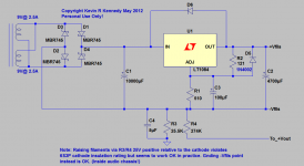
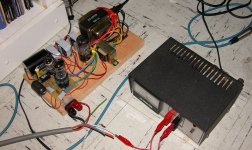
Power Supply (Breadboard Version)
This is the power supply as it currently (and temporarily) exists. Note that despite my best efforts there are a few exposed high voltage points so this is definitely not recommended except in a lab situation..
Should note that as this phono stage design operates on 300V and the raw supply to the regulator is well over 500V that care in its construction and testing are required. (Construction, testing, and use at own risk.)
The design shown in the photograph utilizes a 1.5H choke, and manages a measured output noise and ripple level of 0.35mVrms (300V/35mA load/120Vin @ 60Hz) which is acceptably quiet, with the 5H choke specified in the schematic above the noise levels will be significantly lower if care in construction is taken.
Attachments
Nice. Is R3 (U2) essential? Does it surely oscillate without? Ups input noise.
No, it really doesn't in any meaningful way. Cartridge DCR is likely to be ~1k and the noise adds as power. Given cartridge inductance and reduced shunting of the input resistor at HF, the resistor's contribution is even smaller than small.
Just because I'm a finger-counting mathematician, 60dB above 20mV is 2V, so 54dB is half that, 1V. Seems like it's not insane, it's optimum.
You're off one decimal place.. I get 2.5V out with 5mV in..
 (60dB: 1000X)
No, it really doesn't in any meaningful way. Cartridge DCR is likely to be ~1k and the noise adds as power. Given cartridge inductance and reduced shunting of the input resistor at HF, the resistor's contribution is even smaller than small.
SY is correct, the noise contribution of that 100 ohm resistor is negligible compared to the noise resistance of the cartridge/transformer combo.
No, it really doesn't in any meaningful way. Cartridge DCR is likely to be ~1k and the noise adds as power. Given cartridge inductance and reduced shunting of the input resistor at HF, the resistor's contribution is even smaller than small.
SPU is extremely low DCR I thought.
Why burning a huge drop? Utilizing an existing Tx reason?
Pass tube requires a minimum of 200V for proper operation, it is a series pass after all. I actually get transformers built to spec for most of my designs. Based on ongoing listening experience I still find I prefer this design sonically to some more recent designs. I have not tried the shunt yet..
SY is correct, the noise contribution of that 100 ohm resistor is negligible compared to the noise resistance of the cartridge/transformer combo.
What kind of DCR your SUT secondary has?
SPU is extremely low DCR I thought.
My SPU is a Classic GM E II with a DCR of six ohms, primary SUT dcr is 0.4 ohms through a 16X step up transformer so 1638 ohms equivalent noise resistance (16^2 x 6.4 ohms) for the cartridge and SUT primary.
The transformer secondary DCR is 53 ohms, small enough so that the transformed cartridge and primary DCR is the dominant noise source as it should be.
Nominal output with this transformer at 5cm/sec is about 3.2mV..
Cartridge noise is equivalent to 5.26nVrtHz or 0.74uV over 20K BW which calculates to an SNR of almost -73dB referenced to 3.2mV which is several dB beyond what the medium can do under the very best circumstances.. (And more than 10dB better than most good recordings) - the pre-amp is around -80dB (ref 3.2mV)...
I hate when I'm off by a factor of ten.
Salas, I think this is for MM, not for the SPU.
No, this is for the SPU with SUT, but not just SPU, works fine with MM and HO MC, it was designed to be pretty compatible with anything, highish overload margin and low input capacitance..
(It's been tested with several other cartridges including a MM)56dB gain I thought of MC input. Many with that gain are classified MC. Including an SUT is another ein calc of course.
In my system another 20dB - 26dB of gain would be required for an MC, plus I like the noise margins better this way as you can see from the calculations referenced in a previous post. I like my electronics to be as close to silent as possible.
Actually I haven't, and the 5842 also has a pretty large spread which also has not proved to be an issue in practice. (I have 32 pieces of the 6S3P-EV, but have only looked at 10) I suspect in the case of the 6S3P it depends on what part of the plate curve you operate as well - in this case obviously the range is extremely limited. (And towards the left hand side of the plate curves where mu is pretty consistent)
The two channels are very closely matched (0.1dB) with randomly selected tubes. I was concerned about this issue, but since the tubes are dirt cheap I figured I would just match a bunch if necessary, it hasn't proved to be so far. The interesting thing will be to see how things progress as the tubes age and transconductance falls and grid current possibly increases.
The old D3A/5842 based design this replaced actually had worse channel to channel matching than this one does, at ~0.2dB.
Some interesting information on the 6S3P-EV from the Russian Klausmobile site - the comments and the nice looking curves are what intrigued me in the first place about this tube, the bargain prices clinched the deal. This site is worth a good look in general.
Here: Tube Tester Files - 6S3PEV
Here: Tube Tester Files - 6S3PEV
- Home
- Source & Line
- Analogue Source
- The "Muscovite" 6S3P Tube Phonostage