The RIAA conformance with matched parts is better than +/-0.1dB and bass response is excellent. (Of course I would say that)
Gain is a few dB higher than 50dB @ 1kHz. My intention was something in the vicinity of CD red book maximum output levels at 2 - 5mV @ 5cm/sec velocity. I no longer remember the exact numbers, but the first stage is around 44dB and the second around 33dB, the EQ is passive so there is no issue of running out of gain at the low end, the only issue is the LF pole introduced by the coupling cap to the EQ network, and the basic accuracy of the network design and the components used to implement it. There is quite a variation in 6S3P depending on the grade selected and where/when they were made. I recommend the EV grade as the best sounding and most consistent, important to use ones all from the same manufacturer and preferably same lot - since they are generally sold in bulk this hasn't been a problem.
My line stage has only 4 dB of gain, hence the desire for a lot of gain here. The design is suitable for use with both transformers, HOMC and MM cartridges - since it is a cascode input capacitance is low, with care in layout input capacitance under 50pF is possible. (I seem to recall measuring about 30pF in mine)
I recommend using a transformer or head amp for LOMC cartridges despite the high gain, depending on cartridge output gains of 5X - 20X (14dB to 26dB) is fine, target input voltage of about 4 - 5mV.
I set mine up with a line stage gain of 5 ( OPA2134 ) > volume / balance pots Loudness > 6922 tube gain = 11 > passive tone controls > SS amp gain =10
phono preamp and iphone preamp set to match Pioneer 780 AM / FM output
tube needs 40v p-p to fully drive amp to 85 v p-p tone controls flat
Sound quality is outstanding
phono preamp and iphone preamp set to match Pioneer 780 AM / FM output
tube needs 40v p-p to fully drive amp to 85 v p-p tone controls flat
Sound quality is outstanding
Sounds like a nice set up, interesting mix of tube and solid state. My system is mostly tube, but I have solid state room EQ (pair of old BSS FC-926 Varicurves), some of my newer designs like the strain gauge pre in another thread is hybrid.
Amps are transformer coupled 20W GM70 SE, line stage is transformer coupled using EML 20A dht..
Amps are transformer coupled 20W GM70 SE, line stage is transformer coupled using EML 20A dht..
Kevin - have you found anything in the development of the strain gauge preamp that is worth incorporating into the Muscovite design?
Getting a house ready to sell has taken far longer than expected but I do have filament supplies built and slowly starting the HV supplies.
-Phil
Getting a house ready to sell has taken far longer than expected but I do have filament supplies built and slowly starting the HV supplies.
-Phil
Hi Phil,
The designs are so totally different with such different goals, so actually no. The strain gauge design was intended to be simple and cost effective while offering excellent performance and relatively minimal cost - I was not sold on the strain gauge cartridge and wanted to limit my exposure in the event it was a bust.
I learned a lot I will apply in new designs, but there is nothing really transferable from the strain gauge to the Muscovite given the rather different goals. When I respin the Muscovite for a limited run at the commercial market I will use DC filament supplies for the 12AX7A error amplifiers in the power supplies and possibly EL84/6BQ5 as pass tubes in the PSU. Less likely but possibly a different lower capacitance choke (if I can locate one) in the choke based mu follower output stage - make sure the DCR overall is about the same, an adjustment in the series resistor value might be required. You can make these changes in your current build if you want, those changes at most would result in a tiny improvement in performance, the best passive components you can find and careful layout will take you further than these minor changes alone.
Thank you for the great answer, Kevin. I have all the parts for additional filament supplies, and I'll check out the EL84 as pass tube. I'm following your parts suggestions to the letter.
I'm looking forward to starting the layout but want to be able to focus on that without the current distractions so that will be early December - I'm pretty sure of that this time....
Phil
I'm looking forward to starting the layout but want to be able to focus on that without the current distractions so that will be early December - I'm pretty sure of that this time....
Phil

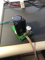
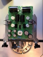
Well, I finally got a start on my Muscovite. Here's a first/rough layout of the power supply on a 6' x 8" protoboard. I not sure if I'll use it or not but would mount the tubes on one side and components on other if I do. Then mount it so the tubes pop thru the top of the chassis. The little board is for preamp filament supply (1 per channel). I tested it at 1.3A (equivalent to 4 filaments for 6S3P-EV) with an electronic load and it looks fine on scope. Heatsink gets to about 60C in free air. I've got similar boards made up for filaments for 12AX7 error amps.
Right now I'm considering 2 chassis from Landmark, each 9"w x 13"d x 4.5"h. That size will be big for the preamp itself but I don't mind a little extra room in case Kevin moves the Muscovite to St Petersburg and needs more space.
Phil
Right now I'm considering 2 chassis from Landmark, each 9"w x 13"d x 4.5"h. That size will be big for the preamp itself but I don't mind a little extra room in case Kevin moves the Muscovite to St Petersburg and needs more space.
Phil
Attachments
I've had to rethink the layout and the filament supplies. I hoped to use the 6V/1A winding on the big Edcor for the 12AX7 filaments but it was barely marginal. About 40 mVRMS ripple on the regulator with a 600 mA load, and it was very close to drop-out at 120 VAC (measured) line voltage. A 25VA/9+9 VAC secondary from Antek (AN-0209) works great. The little boards I was hoping to use for filament regulators won't work as they simply take up to much real estate in the chassis so back to the drawing board on those.
Phil
added in proof: I'll probably just tie the 2A and 1A 6V secondaries together for the 6BQ5 filaments. I phased the transformer secondaries and used Mark Johnson's Quasimodo gizmo to find the best values for snubbers on the regulated filament supplies. Will post values once I confirm the measurements.
Last edited:
I'd be careful about tying those secondaries together, if they differ even slightly in length they will fight each other.
I know what you mean about trying to find the space to fit everything in.. I run into this from time to time. Lately I have started to make my chassis bigger.
I know what you mean about trying to find the space to fit everything in.. I run into this from time to time. Lately I have started to make my chassis bigger.
I am building one of these using Lundahl LL1668 plate chokes. I use an Audient ID14 as ADC for ripping LPs - it has 8k input impedance. Can the Muscovite drive this low impedance or would I need to add an impedance matching buffer? I would use a larger value output cap without the buffer.
Thanks!
Thanks!
- Home
- Source & Line
- Analogue Source
- The "Muscovite" 6S3P Tube Phonostage