Mostly as an academic exercise, I wonder what others think about this design:
It's from this ebay listing from a vendor in China: STEREO 12AX7 12AU7 SRPP CR TYPE RIAA NETWORK TUBE MC / MM PHONO PREAMPLIFIER PCB | eBay
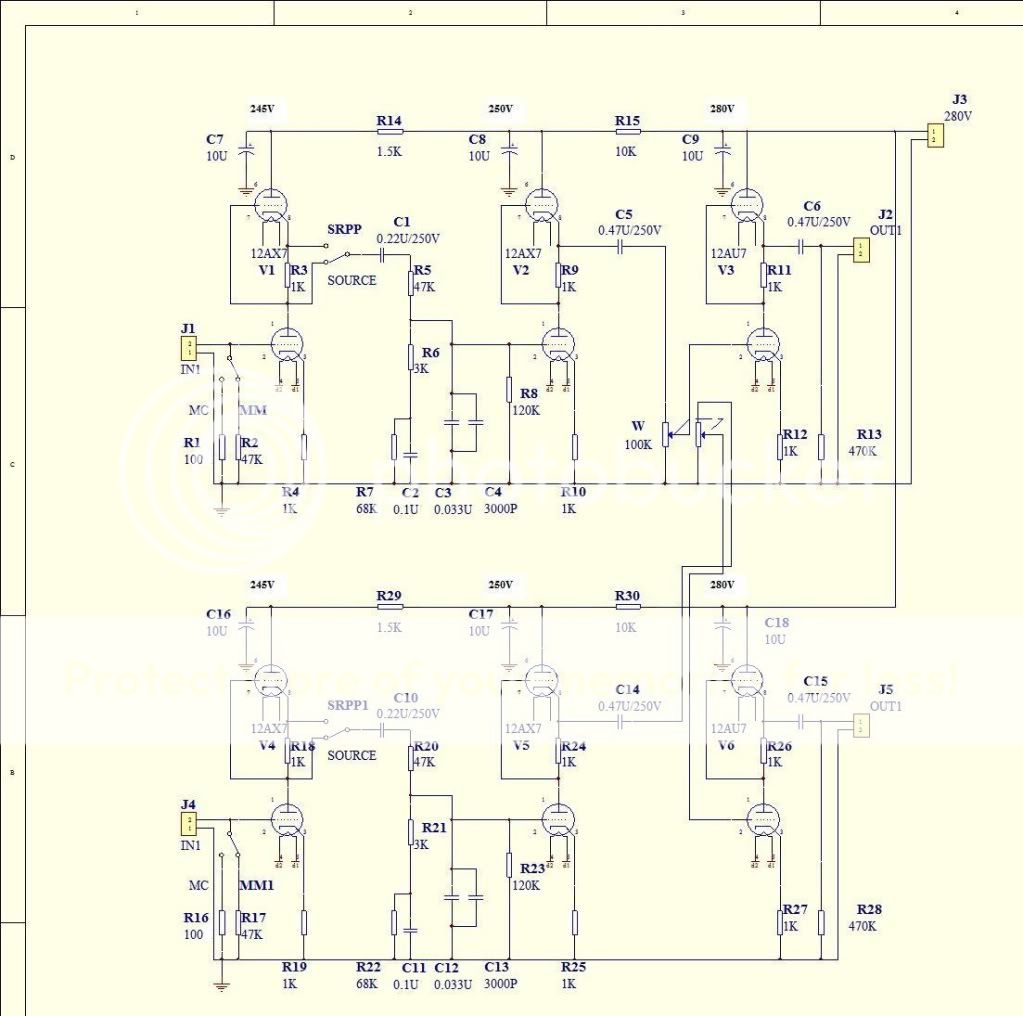
Although I've built all sorts of gear since 2006, I'm still a newbie in terms of really understanding what's going on, especially with phono stages. For example, it looks vaguely similar to the groovewatt, except with SRPP final stage.(?). And the lack of a resistor to the upper grids seems wrong to me (grid current?).
The reason it intrigues me is the use of SRPP, particularly in the last stage. But then just today I read this from SY:
Anyway, please help me understand what's going on, what's good about it, what's not.
Cheers!
It's from this ebay listing from a vendor in China: STEREO 12AX7 12AU7 SRPP CR TYPE RIAA NETWORK TUBE MC / MM PHONO PREAMPLIFIER PCB | eBay
Although I've built all sorts of gear since 2006, I'm still a newbie in terms of really understanding what's going on, especially with phono stages. For example, it looks vaguely similar to the groovewatt, except with SRPP final stage.(?). And the lack of a resistor to the upper grids seems wrong to me (grid current?).
The reason it intrigues me is the use of SRPP, particularly in the last stage. But then just today I read this from SY:
Sy explaining some of what can be learned from Morgan Jones. And now I wonder...why an SRPP is not a good idea for small signal stages
Anyway, please help me understand what's going on, what's good about it, what's not.
Cheers!
The SRPP (it actually isn't an SRPP, but it resembles one) is a standard feature of Chinese EBay vendors. In this circuit, distortion and noise will be poor, RIAA conformance poorer, and the frequency response will be grossly different with switch position. This was not engineered, it was cut-and-pasted with no real understanding of how the circuit works.
Really, you'd do better with the cheap MM phono amp in the RCA tube manual, which isn't terribly good, but is better than this mess with a much lower parts count. And I'll repeat my recommendation of Morgan's treatment of phono preamps- he's very thorough and clear, and unfortunately, it's not something that can be easily compressed into a few paragraphs of a forum post.
Really, you'd do better with the cheap MM phono amp in the RCA tube manual, which isn't terribly good, but is better than this mess with a much lower parts count. And I'll repeat my recommendation of Morgan's treatment of phono preamps- he's very thorough and clear, and unfortunately, it's not something that can be easily compressed into a few paragraphs of a forum post.
It's a pretty bad design overall, neither switch position is going to result in good performance with a 12AX7A, the RIAA network impedances are just too low. (Insufficient current available) Even in SRPP position the source impedance is going to be in the range of 10K, and in the other something over 100K.. I can't even begin to imagine how bad this thing could sound, if by some measure it doesn't - it'd have to be the mark of providence..
Wow, answers from two of my most revered posters! Thank you. I am wading through Morgan Jones, but I'm not through the first read yet, and it'll take 2-3 reads before I really understand. I'm kinda thick about this stuff really. It takes me a while.
Anyway, I'm constantly fascinated by the Chinese offerings on ebay since some are obvious rip-offs of commercial units (one is obvious rip-off of the Hagermann Bugle, which (the original) I own) and they all claim, obviously, to be great solutions. I haven't tried any of them yet, and I'm not especially interested is trying one as long as there's a TubeCad, Boozhound, ESP or other offering out there. Still, I look at schematics a lot and try to dissect them to the best of my abilities (as limited as they are) just for the practice.
I hadn't even considered the RIAA compensation portion of this schematic as I'm not at all ready to do the grunt work on that yet. But I seem to grasp more theory when I have a schematic to start from, so this seemed like a good starting point. Now, though, it seems like this isn't even worth a theoretical discussion.
Unless someone wants to pile on, I'll consider it closed and read more of Morgan Jones instead of thinking about this any more...
Oh, and I've considered for a while trying an Eli Duttman variation of the RCA circuit, so I'll go back to it and think about it some more...
Thanks!
MJ is certainly worth a few read-throughs. He's very good about showing exactly how things are done and the trade-offs, but doesn't gloss over the important points. It takes some effort, but it's worth it.
Morgan says (and I agree) that phono stages are the single most difficult piece of electronics to design, so don't feel thick- it's a hard problem for anyone. Even Kevin.
Morgan says (and I agree) that phono stages are the single most difficult piece of electronics to design, so don't feel thick- it's a hard problem for anyone. Even Kevin.
I love China, great place to travel, lovely people. More small business entrepreneurship than any where in the world in my humble opinion, but I have been consistently disappointed with anything bought from these guys. Pretty sure I know the company, If not, they all copy and sell the same stuff. Its how it works.I am in a similar business so No disrespect intended. I tried two phono stages, psu. gave up disgusted.
I have just built the Tetra phono Pre amp. Great Board. Very confusing Instructions, and after a couple of weeks of F$%#%^& about I love it.
I expect that that is as good as it gets at the level that I am at.
Imagine that translated into chinese
I agree that valve phono stages are the pinnacle.
mick
Yes, the SRPP/SOURCE switch is guaranteed to give the wrong frequency response in at least one position because it changes the source impedance seen by the RIAA network. That alone guarantees that either the designer did not understand what he was doing or he was deliberately just 'pushing sales buttons' instead of aiming for good sound.
The unbypassed SRPP is a poor phono inout stage because it guarantees poor PSRR. The 12AX7 SRPP is heavily loaded by the volume pot, so some distortion is guaranteed.
This item comes with more solid guarantees than many Chinese goods!
The unbypassed SRPP is a poor phono inout stage because it guarantees poor PSRR. The 12AX7 SRPP is heavily loaded by the volume pot, so some distortion is guaranteed.
This item comes with more solid guarantees than many Chinese goods!
Yes, the SRPP/SOURCE switch is guaranteed to give the wrong frequency response in at least one position because it changes the source impedance seen by the RIAA network. That alone guarantees that either the designer did not understand what he was doing or he was deliberately just 'pushing sales buttons' instead of aiming for good sound.
The unbypassed SRPP is a poor phono inout stage because it guarantees poor PSRR. The 12AX7 SRPP is heavily loaded by the volume pot, so some distortion is guaranteed.
This item comes with more solid guarantees than many Chinese goods!
Yeah, I get how the switch will impact RIAA in at least one position. Guess it'd be too much to expect two different RIAA circuits, one for each position... Re: the unbypassed SRPP, are you talking about the upper cathode resistor, the lower, or both? How does that influence PSRR? I need to get MJ out again soon!
And I don't really get the volume pots. I don't know how to calculate gain for this (a good exercise, I know) so I don't really understand what the final stage is for. To bring the gain up to a reasonable MM level? And the MC switch seems only to switch the input loading. Where's the gain for the MC, or is that part of the first stage SRPP switch? Or does it somehow work in conjunction with the pot before the 12AU7?
Ahhhhhh. My head hurts...
Cheers.
In an SRPP the upper cathode resistor is always unbypassed, otherwise it is not an SRPP. If the lower cathode resistor is bypassed then you get more gain, less noise, better PSRR, but possibly higher distortion for bigger signals. For small signals like phono input the lower cathode should normally be bypassed.
For symmetric unbypassed SRPP the stage gain is mu/2. The first stage switch does not change gain by much - I can't see the point of it. Simply adding a low value input resistor does not change an MM stage to an MC stage: the gain, noise and overload requirements are different. This circuit has a mid-band gain of about 50 x 50 x 8 / 15 = 1500. Possibly about right for MC, too high for MM.
For symmetric unbypassed SRPP the stage gain is mu/2. The first stage switch does not change gain by much - I can't see the point of it. Simply adding a low value input resistor does not change an MM stage to an MC stage: the gain, noise and overload requirements are different. This circuit has a mid-band gain of about 50 x 50 x 8 / 15 = 1500. Possibly about right for MC, too high for MM.
Hi DF96,
I follow the bit about the 50 x 50, (0.5 x mu) but am puzzled at where the 8/15 came from.
The way I look at this is that midband (1kHz) the gain is -20dB relative to 20Hz where the network no longer has appreciable attenuation.
The discussed SRPP has a source impedance at the cathode of roughly 10K so that in conjunction with the voltage divider formed by R5 and R8 gives you -3.5dB relative to the unloaded SRPP for a total loss at 1kHz of -23.5dB.
The overall available gain is 2500X or 68dB before the losses and EQ are added.
I think overall gain is therefore going to be in the region of 44.5dB which is well within the accepted limits for a MM cartridge. Note that the heavy loading on that first SRPP will probably further reduce the gain so it could be several dB lower than my estimate.
Still IMO a lousy approach, and the switch is a bad idea.. (useless)
@ Carlp
The last stage is essentially a line stage without a source selector, it can be omitted..
If you are seriously looking at building something check out either the Valve Itch Phono here: http://www.diyaudio.com/forums/analogue-source/140635-valve-itch-phono.html
Or mine here: http://www.diyaudio.com/forums/analogue-source/213769-muscovite-6s3p-phonostage.html
Either of these will run circles around the discussed design and plenty of help is available.
@ Carlp
The last stage is essentially a line stage without a source selector, it can be omitted..
If you are seriously looking at building something check out either the Valve Itch Phono here: http://www.diyaudio.com/forums/analo...tch-phono.html
Or mine here: http://www.diyaudio.com/forums/analo...honostage.html
Either of these will run circles around the discussed design and plenty of help is available.
Thanks, Kevin. I thought the last stage was essentially a line stage, but it's weird how they only mention the phono stage in the ad - maybe their documentation is better(???). Anyway, I'm not, and hadn't been prior to this thread, thinking about building this. I was curious about the schematic b/c SRPP (which I've never heard in any form) has me intrigued.
I am very much thinking about building a tube phono stage, and have looked at the Valve Itch project. I'll also look at yours, thanks (at a quick glance yours looks very interesting but I don't understand it...yet). I started a build of Fred Nachbaur's phono stage: http://www.dogstar.dantimax.dk/tubestuf/graphics/phono-m.gif
because I built his SE amp and loved it (it was my first electronics project). But I ran into transformer buzz and other problems and it sits unfinished in a box. Then I heard all the noise about active EQ vs passive. May never get back to it...
I am also not above a PCB project like the TubeCad Tetra or Aikido phono stages, but my first love is DIY point-to-point.
Thanks again!
Carl
- Status
- This old topic is closed. If you want to reopen this topic, contact a moderator using the "Report Post" button.
- Home
- Source & Line
- Analogue Source
- SRPP phono stage?