I have recently discovered strain gauge cartridges after worrying about MM vs MC cartridges for the last 30 years. Happy to say that my newly acquired Win strain gauge is the best thing I've ever heard, even though its about 40 years old. Sorry to say that I've wasted a long time listening to sub-standard cartridges. Oh well.
Anyway, the Win came without a line stage so I decided to build my own. The lack of equalisation is a bonus, though requirement for balanced output is a complication. Anyway my circuit is attached, with a few notes.
1. This is battery powered. I'm too lazy to build shunt regulators, and too stupid to understand Akido-style circuitry. Batteries take no time to implement and are quiet.
2. Idss of my matched jFETs is 12.5mA, I have gone with standing current of 10mA. CCS is 20mA, adjust on test.
3. Upper cascode resistor goes to output rather than B+. Learnt this trick from John Broskie (Nelson Pass also uses this in Zen V8 or 9). This will reduce distortion and reduce gain, luckily i still have plenty of gain to drive my power amp in this "ultra-linear cascode" configuration.
4.. Originally I used output capacitors to block DC, I am now using a 1:1 transformer (Lundahl 1527XL) which is much more transparent, I prefer it to the caps I had
5. The variable resistor across the output is actually a 24position switch with resistors ranging from 100k down to 50R (salvaged from an old switched attenuator, resistor values have not been calculated to give precise steps in this application). This provides variable gain, switches are necessary to ensure close channel matching. Therefore I have no preamp any more, just a source selector. Also allows me to set recording level for needle drops (into my EMU 1212M sound card).
That's about it. Sounds brilliant, as do all our own creations.
Attachments
3. Upper cascode resistor goes to output rather than B+. Learnt this trick from John Broskie (Nelson Pass also uses this in Zen V8 or 9). This will reduce distortion and reduce gain, luckily i still have plenty of gain to drive my power amp in this "ultra-linear cascode" configuration.
Who in turn learnt it from William Z Johnson (Audio Research).
It's a partial cascode, first used by WZJ in US 4647872 in 1985. This is a form of local feedback.
If you design carefully, you can incorporate the EQ mentioned by SY in this part of the circuit.
Have you measured the frequency response yet? Wasn,t this one of the issues with the strain gauge concept along with poor seperation figures?
I remember the EK-1 from.., Robertson? Every time you bought a new Panasonic cart, you had to send the control center back for recalibration
The idea of extremely low moving mass should have favored the strain gauge over all the moving coils we see today
So what is the achillies heel of this promising idea that never quite took off?
BTW I have had 4 MC,s made by SAo Win and found them exceptional but never tried his strain model- alas..
Regards
David
So what is the achillies heel of this promising idea that never quite took off?
The installed base of noncompliant preamps. Audiophiles hate the idea of being tied to one preamp, that's much less fun. Technically, it's a great approach.
The Win cartridge was brilliant, one of my all-time favorites. But... you still need EQ. Not RIAA, since the output is displacement sensitive, but you have to EQ for the midrange where RIAA has a zero and a pole.
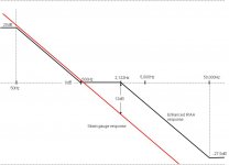
Firstly I will say that I have been using this cartridge with no equalisation for a few months, and there are no obvious response errors - but maybe I have cloth ears!! I have looked looked at bode plot of RIAA curve vs strain gauge reponse and it appears to me that at a theoretical level, assuming that strain gauge matches RIAA between 50 and 500Hz:It's a partial cascode, first used by WZJ in US 4647872 in 1985. This is a form of local feedback. If you design carefully, you can incorporate the EQ mentioned by SY in this part of the circuit.
- Strain gauge will suffer from lack of hf, and needs a shelf lift of over 10dB above 2,122 kHz. Increasing gain is required above 50kHz to match the enhanced RIAA curve
- Strain gauge will have too much bass below 50Hz and needs a LF roll off.
Have I got this right? In reality, the actual RIAA response is much flatter than a bode plot and response errors are not noticeable (well i would expect to hear 10dB).. I'll have to think how I can engineer something into the partial cascode feedback loop - anyone got any ideas on how to boost hf? Maybe a variable adjustment, so I can set it for best sound, and increase each year as my hearing fades.
Attachments
Last edited:
No replies?
I just wanted to say that I think you are right. I have an old Technics SG I would like to try, but my Technics CD-4 decoder did not work to well, so I am planning to use a preamplfier PCB I have laying around, just biasing the cartridge. That should work. But as you, I realized the frequency response could not be ideally flat.
Best regards
RK
4. Originally I used output capacitors to block DC, I am now using a 1:1 transformer (Lundahl 1527XL) which is much more transparent, I prefer it to the caps I had.
Yes, caps introduce their own sonic signature (and can be fearfully expensive!
 ) but they have a far wider bandwidth than a transformer. The only spec I could find for the Lundahl 1527XL said that its upper rolloff point was 150KHz - which IMO is not high enough.
Plus they cause a signal loss.
Regards,
Andy
Last edited:
150kHz is not high enough? What source are you listening to, even if its 192kHz then there's nothing above 96kHz.Yes, caps introduce their own sonic signature (and can be fearfully expensive!
Plus they cause a signal loss.
Regards,
Andy
Oh, I just checked the spec sheet - pass band is 10 hz to 150 kHz +/- 0.2kB. You can really hear 0.2dB drop at 150kHz?
pass band is 10 hz to 150 kHz +/- 0.2kB. You can really hear 0.2dB drop at 150kHz?
I would say no!
I had thought the "pass band" meant the -3dB frequencies, not the 0.2dB frequencies.BTW, the spec sheet shows a 0.4dB loss at the mid-band. Does this imply the loss is different at different frequencies?
The reason I am interested is that I can save a bundle if I can use LL1527s instead of output coupling caps, to stop DC passing, in my phono stage. I have been using $350 a pair caps!One point, though ... the spec sheet specifies some particular input & output impedances - source 800ohms , load 4Kohms. This seems to me to not be comparable to the real-world situation which a phono stage is in ... eg. a phono stage feeds a line-stage preamp ... which is likely to have a Zin of 10-50Kohms?
Regards,
Andy
Andy, I have always assumed that the 0.4dB loass at mid band implies a constant loss across al freq due the DC resistance of the TX. IE if you had a perfect 1:1 tx then the gain is 1, but real world losses mean that this tx has a gain of -0.4dB at mid band. Then the pass band is referenced to this point, ie Lundahl quote 20hz to 150kHz +/- 0.2dB referenced to the mid band.I would say no!
BTW, the spec sheet shows a 0.4dB loss at the mid-band. Does this imply the loss is different at different frequencies?
One point, though ... the spec sheet specifies some particular input & output impedances - source 800ohms , load 4Kohms. This seems to me to not be comparable to the real-world situation which a phono stage is in ... eg. a phono stage feeds a line-stage preamp ... which is likely to have a Zin of 10-50Kohms?
Regards,
Andy
In answer to your question about replacing caps with the Lundahl LL1527 - I would not do this if your amp is single ended. If you look at my circuit you will see that it has a balanced output so there is NO DC passing through the tx. If you have a single end output, and connect the tx between output and ground, there will be a DC voltage across the tx and hence a DC current - not a great outcome.
If your line stage has a Zin of 50k, then you can provide the 4k load for the tx by putting a resistor across the output of the tx - that's the way I do it. 4K resistor would be OK, this will give a total resistance of 3.7k. As long as the output of your phono stage is 1k or less then you will have no problems (as longs as its balanced!!)
In answer to your question about replacing caps with the Lundahl LL1527 - I would not do this if your amp is single ended. If you look at my circuit you will see that it has a balanced output so there is NO DC passing through the tx.
Thanks for this additional info, mate. Yes, my phono stage is single-ended, not balanced. I obviously had it wrong - I thought it was possible to use a series coupling transformer as an alternative to a series coupling cap, to stop DC offset passing though.
Oh well, I'll have to go back to using expensive 1uF caps!
Regards,
Andy
150kHz is not high enough? What source are you listening to, even if its 192kHz then there's nothing above 96kHz.
Oh, I just checked the spec sheet - pass band is 10 hz to 150 kHz +/- 0.2kB. You can really hear 0.2dB drop at 150kHz?
I have found that over complicating a circuit with many components to try and get an absolutely flat frequency response when not much correction was needed, often does more harm than good. So I agree with your point
I've been happily living with my strain gaugue amp from post #1 for a couple of years, but have some time off work recently and time to play around. Key things that have been bugging me
1. The original circuit is lacking some gain.
2. The circuit is single-end in, differential out. I'm a tidy person and want everything to be differential all the way (my power amp is also differential).
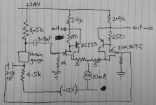
So I have rebuilt the strain gauge amplifier as per attached diagram. Key changes are:
a. grounded source fet (2SK369) has been converted into a complementary feedback pair with the addition of a pnp transistor (BC560). I tested this and measured 1,800x gain with an input of 5mV!! Source resistors have been added to bring down gain to a sensible level.
b. Strain gauge is sandwiched between equal resistors to provide a differential output across the strain gauge. There will be DC at each end of the SG so capacitors are required to couple the differential output to the long tail pair.
c. The coupling caps are actually an advantage. It is claimed that strain gauge cartridges don't need eq as the natural 6dB roll off is reasonably close to the RIAA curve. However, below 50Hz the RIAA curve is flat. The 6dB roll off below 50Hz afforded by the cap (3.18uF with 1Meg), together with the 6dB increase below 50Hz of the strain gauge, provides a flat response below 50Hz as required by RIAA curve.
4. RCA connectors on the input of the pre-amp have been replaced by 3.5mm TRS connectors.
So how does it sound? The biggest change is the way that the circuit handles surface noise. Previously, the pre-amp emphasised high freq surface noise and older records could sound almost hissy. Now, the differential input seems to cancel surface noise - crackles and pops are still evident if the record is less than perfectly clear but the hiss of surface noise that starts as soon as the needle hits the groove, has gone. Frequency extension both up and down is excellent. The coupling caps look quite small but as described above, the value is correct and there is no lack of bass. While surface hiss has gone, this is not at the expense of high frequency response, which is at least as good as it was. Probably better.
So I am very happy with upgrade, and the changes are in too stay.
Note: As before.
1 Output is coupled to power amp via Lundahl 1527XL transformer.
2 There is no pre-amp, only a source switch box. Volume control is effected by 24 position switched resistors across the output (so this is a true gain control, not an attenuator).
1. The original circuit is lacking some gain.
2. The circuit is single-end in, differential out. I'm a tidy person and want everything to be differential all the way (my power amp is also differential).
So I have rebuilt the strain gauge amplifier as per attached diagram. Key changes are:
a. grounded source fet (2SK369) has been converted into a complementary feedback pair with the addition of a pnp transistor (BC560). I tested this and measured 1,800x gain with an input of 5mV!! Source resistors have been added to bring down gain to a sensible level.
b. Strain gauge is sandwiched between equal resistors to provide a differential output across the strain gauge. There will be DC at each end of the SG so capacitors are required to couple the differential output to the long tail pair.
c. The coupling caps are actually an advantage. It is claimed that strain gauge cartridges don't need eq as the natural 6dB roll off is reasonably close to the RIAA curve. However, below 50Hz the RIAA curve is flat. The 6dB roll off below 50Hz afforded by the cap (3.18uF with 1Meg), together with the 6dB increase below 50Hz of the strain gauge, provides a flat response below 50Hz as required by RIAA curve.
4. RCA connectors on the input of the pre-amp have been replaced by 3.5mm TRS connectors.
So how does it sound? The biggest change is the way that the circuit handles surface noise. Previously, the pre-amp emphasised high freq surface noise and older records could sound almost hissy. Now, the differential input seems to cancel surface noise - crackles and pops are still evident if the record is less than perfectly clear but the hiss of surface noise that starts as soon as the needle hits the groove, has gone. Frequency extension both up and down is excellent. The coupling caps look quite small but as described above, the value is correct and there is no lack of bass. While surface hiss has gone, this is not at the expense of high frequency response, which is at least as good as it was. Probably better.
So I am very happy with upgrade, and the changes are in too stay.
Note: As before.
1 Output is coupled to power amp via Lundahl 1527XL transformer.
2 There is no pre-amp, only a source switch box. Volume control is effected by 24 position switched resistors across the output (so this is a true gain control, not an attenuator).
Attachments
Last edited:
Hi
Have been planning to build your original design (post #1) ever since seeing it over on Vinyl Engine. It was more appealing than Flavio's opamp design because it had a lot in common with the fet-based opamps inside my active crossover.
You commented at the time that the gain was just enough for your Win, so for my Panny SG, I was going to reluctantly add SU transformers, so it's cool that the new version has increased gain. But I bought BL Toshibas at the time so am wondering if they're ok to use instead of GR's, or are there some value changes needed.
Appreciate you sharing your efforts for others who also want to max the performance of their quirky but amazing strain gauge cartridges.
Hi, 2SK369 BL will work fine - no adjustments required. Just match Vgs at 1mA.
I also recommend that you match Vbe in the pnp transistors at 4mA. They control the current through the jfet via drain resistor (650 ohms). So matching Vbe will keep the current at 1mA in both jfets..
Also, you can adjust gain with the source resistors. 5ohm gives heaps of gain with the Win (much more gain than I had with the original circuit, with no degeneration). It may be enough gain for the panasonic. But if not you can reduce to 2 or 3 ohms if you need even more gain.
I've been playing lots of records in the last week, and really enjoying the new gain stage. Hope you enjoy it as well.
- Status
- This old topic is closed. If you want to reopen this topic, contact a moderator using the "Report Post" button.
- Home
- Source & Line
- Analogue Source
- Strain Gauge jFET Pre-amp