Attached is an RIAA preamp circuit that came out of the work I've been doing (documented in the analog line forum) with feedback connected mosfets used to simulate or fake a SIT, which has a triodish characteristic. That led to a "pseudo-Aikido" using mosfets and jfets that needed feedback to tame its gain. That circuit is used in the second stage of this preamp. It's the first feedback RIAA amp I've designed in years. It probably won't be quite optimal with respect to noise because of the high value feedback resistors. However, those resistors are in the second stage, which may somewhat mitigate their effect.
The second stage provides a pretty optimal load for the SRPP first stage. One could also use a simple cascoded common source 2SK170 at the input, but a follower would be needed. I've laid out my circuit board for both input circuit types. The one thing standing in the way of going ahead with this is putting together a suitable 2n8 cap for the RIAA filter. I already have the 10nF caps. I should be able to scrounge something fairly soon.
At any rate, this may not be the hottest circuit in town but it's food for thought.
Attachments
Last edited:
I found the fixings for my 2n8 cap (high quality 2n7 + 100p polypropylene), so the board is laid out, and will get listened to sometime down the line.
Wrenchone,
Looks good, keep us posted.
DT
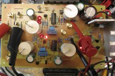
I'm actually stuffing a board for one of these preamps. The power supply/regulator came up without any hitches today, and I may finish selecting and stuffing the rest of the jfets and mosfets this weekend.
Actual listening may not happen until I put together a special test chassis (no selector switch, just a pair of RCA jumpers to switch between RIAA preamp and line source). The first pairing of test modules in the box will be this preamp and a "MOSFET-Schade" line amp.
Actual listening may not happen until I put together a special test chassis (no selector switch, just a pair of RCA jumpers to switch between RIAA preamp and line source). The first pairing of test modules in the box will be this preamp and a "MOSFET-Schade" line amp.
I finished selecting the jfets and stuffing the proto board of this preamp. Things balance out sufficiently well that I will hook it up to the gain-phase analyzer at work when time permits to test gain and channel-channel balance. I will probably change R14 to ~120k to better center the second stage output.
This amp is still not optimal because of the high impedance RIAA feedback network, but it's an interesting topology and deserves at least a cursory listen. I suspect that the second stage will provide fairly optimal loading for the PN4393 SRPP input stage.
This amp is still not optimal because of the high impedance RIAA feedback network, but it's an interesting topology and deserves at least a cursory listen. I suspect that the second stage will provide fairly optimal loading for the PN4393 SRPP input stage.
Attached are the gain-phase plots, done with an HP4194A with 0.5 mV input. The gain is a little on the high side, but both sides match to within 0.3 dB.
It occurs to me that the load on the first stage SRPP is still a little lighter than optimal, so I can reduce the impedance of the second stage feedback network, pulling down the overall 1 kHz gain closer to the desired 40 dB and reducing 2nd stage noise contribution. Before I make that change, I'll probably listen to the thing as-is.
It occurs to me that the load on the first stage SRPP is still a little lighter than optimal, so I can reduce the impedance of the second stage feedback network, pulling down the overall 1 kHz gain closer to the desired 40 dB and reducing 2nd stage noise contribution. Before I make that change, I'll probably listen to the thing as-is.
Attachments
Similarity to Creek's SRPP version with BjT's
http://www.diyaudio.com/forums/analogue-source/151527-how-convert-creek-obh-8-mc-cartridges.html
http://www.diyaudio.com/forums/analogue-source/151527-how-convert-creek-obh-8-mc-cartridges.html
An interesting convolution - I'll have to redraw it (always a good first step for understanding an unfamiliar circuit) and stare at it a bit, but the designer looks as if he is taking advantage of the high gm of the bipolar to squeeze all the juice out of a single SRPP gain stage. I have a long thread on jfet srpp in this forum, with more modest gain per stage.
In this particular preamp, I'm taking advantage of the lowish impedance of the second amp stage to optimally load a hotly biased (~10 ma) PN4393 first stage. In this first incarnation, the impedance is a little high on the second stage feedback network, and it looks like I can reduce it considerably for optimal performance (at least, by what PSpice says) for the first stage, and lower noise for the second half. Part of this exercise will be to check PSpice against what a real analyzer says, and also, what the listening characteristics will be like for this circus freak/chimera.
In this particular preamp, I'm taking advantage of the lowish impedance of the second amp stage to optimally load a hotly biased (~10 ma) PN4393 first stage. In this first incarnation, the impedance is a little high on the second stage feedback network, and it looks like I can reduce it considerably for optimal performance (at least, by what PSpice says) for the first stage, and lower noise for the second half. Part of this exercise will be to check PSpice against what a real analyzer says, and also, what the listening characteristics will be like for this circus freak/chimera.
In the jfet SRPP thread (accessible right here in the "analog source" forum), I took a brief look at SRPP preamps using high gm jfets (they had a lot of gain). The circuit that teiffbassuebertr links to a couple of posts previous might be interesting using some high gm jfets in SRPP with equalization applied in-stage , and some modest amplification/buffering afterwards.
Right, he said - yet another project when my bench is already littered with stuff yearning towards completion. Well, as far as I have heard, no one has taken a hammer and broken all those busy little fingers out there (well, they should be busy), so they can take a look at the posited bipolar circuit and transpose it into jfet-land, mayhaps losing some nasty electrolytics along the way. What? You're waiting until I do it and offer a kit with parts and all that ? Ha! You'll be waiting quite a while, then... Call it a taunt, call it a challenge, call it anything you like. Start a thread.
Right, he said - yet another project when my bench is already littered with stuff yearning towards completion. Well, as far as I have heard, no one has taken a hammer and broken all those busy little fingers out there (well, they should be busy), so they can take a look at the posited bipolar circuit and transpose it into jfet-land, mayhaps losing some nasty electrolytics along the way. What? You're waiting until I do it and offer a kit with parts and all that ? Ha! You'll be waiting quite a while, then... Call it a taunt, call it a challenge, call it anything you like. Start a thread.
Last edited:
- Status
- This old topic is closed. If you want to reopen this topic, contact a moderator using the "Report Post" button.
- Home
- Source & Line
- Analogue Source
- Another RIAA Preamp