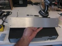
Now the front panel. I often makes my own. They are maybe not perfect, but are easy to make, look good and cheap. I start with a 1/4'' aluminum plate from the metal scrap yard. You can get a fairly large scratched plate for a song. Look around and I'm sure you'll find one too. Don't worry about scratches. If they are not too deep they will go away.
First using a none ferrous metal blade, and a bench saw cut the front plate. Make it large so you can drill mounting holes in it for the sanding next. WARNING, protect yourself very well and work with great care. Use cutting oil and move the metal slowly through the blade. To protect myself I used a full lab overcoat, cap, safety goggles, hear muff, full face protection mask, gloves, etc. Don't let any skin exposed, there will me aluminum metal chips everywhere! If you don't know what you're doing, don't even try it! I did it for years without any issue, cutting up to 1/4'' aluminum plate at home.
Once you have your plate (slightly longer as I said) drill mounting holes and mount it on a wood bench (I use a BB workmate). Then prepare some soap water (I used dish soap) and a hand band sander. I use a simple 3'' wide from Sears. You then simply put some soap water on the aluminum and using very coarse sanding paper (80 in my case) you sand the metal. The soap water add some lubrication, and the coarse paper will attack the surface leaving a nice and tough brushed finish. ALWAYS brush in the same direction to get a nice finish, usually the longer one.
Then using a bench sander, sand the plate sides to remove the bad saw cuts.
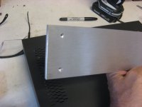
Finally plan your mounting hardware. I used some nice stainless steel hex screws that I mount recessed in the plate.
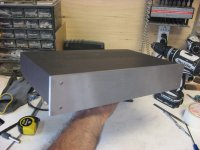
Check my end result. I started with a piece of junk from the scrap yard, and I got this in about half an hour of work. Not bad at all")
First using a none ferrous metal blade, and a bench saw cut the front plate. Make it large so you can drill mounting holes in it for the sanding next. WARNING, protect yourself very well and work with great care. Use cutting oil and move the metal slowly through the blade. To protect myself I used a full lab overcoat, cap, safety goggles, hear muff, full face protection mask, gloves, etc. Don't let any skin exposed, there will me aluminum metal chips everywhere! If you don't know what you're doing, don't even try it! I did it for years without any issue, cutting up to 1/4'' aluminum plate at home.
Once you have your plate (slightly longer as I said) drill mounting holes and mount it on a wood bench (I use a BB workmate). Then prepare some soap water (I used dish soap) and a hand band sander. I use a simple 3'' wide from Sears. You then simply put some soap water on the aluminum and using very coarse sanding paper (80 in my case) you sand the metal. The soap water add some lubrication, and the coarse paper will attack the surface leaving a nice and tough brushed finish. ALWAYS brush in the same direction to get a nice finish, usually the longer one.
Then using a bench sander, sand the plate sides to remove the bad saw cuts.
Finally plan your mounting hardware. I used some nice stainless steel hex screws that I mount recessed in the plate.
Check my end result. I started with a piece of junk from the scrap yard, and I got this in about half an hour of work. Not bad at all
Attachments
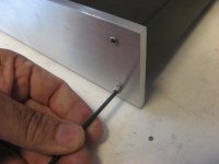
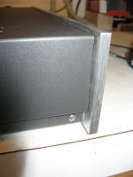
I was forgetting, you may need to adapt a little the rest of the case for the new front panel. Here I cut away the small metal tongue that was locking into the original plastic front panel, so the top was loose on the front. I added a small screw to solve that.
We can see a detail of the front side finish.
We can see a detail of the front side finish.
Attachments
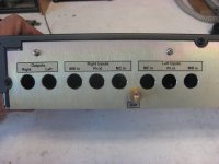
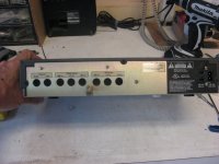
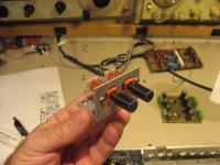
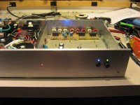
The rear panel now. Problem with a recycled case is often the rear panel that doesn't match at all your needs. Easiest thing to do is naturally to build a new one. I usually keep the original as a back plane. It fits nicely the rest of the mechanical assembly and is a nice base for a simpler rear panel, in this case a piece of recycles aluminum, again
I'm using the same RCA connector than my SVP-2, minimum metal, very nice. They are mounted on the pcb only and don't touch the rear panel. I added P-Touch labels for the identification. On the left you can see that I kept the original AC input connector.
I'm using the same RCA connector than my SVP-2, minimum metal, very nice. They are mounted on the pcb only and don't touch the rear panel. I added P-Touch labels for the identification. On the left you can see that I kept the original AC input connector.
Attachments
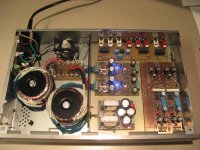
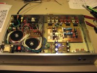
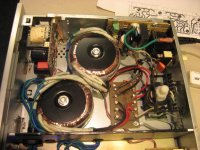
Inside Layout. Naturally you first need to find out if the case you're using will accept all the parts you need to install in it, Ha the obvious, but that you may forgot, I know
This a view of my first inside layout on the left. The power transformers on one side, and the preamp circuits on the other, but check the mistakes
The small p-t-p lights dc supply contains two small transformers (from my surplus). It is now on the preamp side, not optimal I'm afraid.
Once everything was mounted, I didn't like the location of the preamp board inputs and the different support pcb. MC inputs were too far away, low noise supplies were at the other end as well. Not good at all. And I was close to the choice of front panel controls for my switches (MC/MM selector and Mute). I was planning to use simple rocker switches, but decided instead to use old NOS push button switches that I had in my stock for year. Well, the preamp board was in the way. Once again I was too fast on the drilling
Time to go back and do it again...On the right you can see the final design, much better. But still a lot of work before I can go there.
Attachments
Last edited:
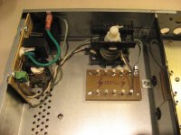
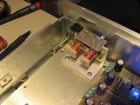
Sometime the smallest things are the hardest to make. In order to relocate the small 9V light supply, I had to make a special mounting bracket so I can install it vertically into the transformers section.
I used a small parts of aluminum U-channel that I cut and sanded to size. The small supply fits now perfectly in the last free cavity of this section.
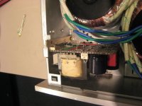
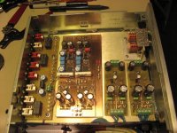
I also added two views of this section. One is showing the standoff PCB use to connect all the transformer primaries (and 110/220V selection if needed). We can see my own version of the ES Ayre Audio line filter and also the rubber grommets that I installed in the steel mid-wall to pass safely the transformer secondary lines. Last picture is the final power section with the power on toggle switch mounted on the rear...
All these small details took hours to make...
I used a small parts of aluminum U-channel that I cut and sanded to size. The small supply fits now perfectly in the last free cavity of this section.
I also added two views of this section. One is showing the standoff PCB use to connect all the transformer primaries (and 110/220V selection if needed). We can see my own version of the ES Ayre Audio line filter
and also the rubber grommets that I installed in the steel mid-wall to pass safely the transformer secondary lines. Last picture is the final power section with the power on toggle switch mounted on the rear...All these small details took hours to make...
Attachments
Last edited:
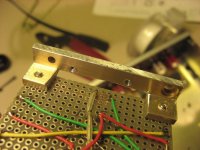
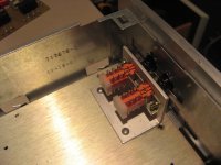
And now the final details, the push button selectors. These nice NOS switches take a lot of work to install properly. It is not bad enough that the new 1/4'' front panel had to be perfectly drilled to fit the switches location. They also need to be precisely located to be actuated correctly. I used a small piece of aluminum L-shape to mount the switches in place. Nice and very rigid. I installed it on the sub mounting plate, then locate the holes to drill on the front plate from behind. The holes were then drilled. The final fit is very good.
There are two switches, one for MC/MM selection, the other for the Mute. In the MM position, the internal MC section and light supply is turn off, making a Standby Mode for the MC section, the rest of the preamp staying powered at all time. Simply push the Mute, than select MC to be in standby... The rear panel RCA PCB contains the needed relays to switch locally the MC and MM inputs, control the light supply and the Mute relay connected at the outputs. There is a 5V local supply on this PCB to further insulate the preamp supplied from the relays power-on clicks.
There are two switches, one for MC/MM selection, the other for the Mute. In the MM position, the internal MC section and light supply is turn off, making a Standby Mode for the MC section, the rest of the preamp staying powered at all time. Simply push the Mute, than select MC to be in standby... The rear panel RCA PCB contains the needed relays to switch locally the MC and MM inputs, control the light supply and the Mute relay connected at the outputs. There is a 5V local supply on this PCB to further insulate the preamp supplied from the relays power-on clicks.
Attachments
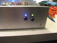
and the led indicators... There are three front panel indicators:
-A center power-on red led supplies from one of the low noise supply, just after the rectifier and before the regulator...
-One led over each switch. These leds are special. From the front you can see that they are two colors, a different color per selection, One for MC or MM, one for Mute or un-Mute. They are not two color leds, but simply two leds mounted back to back, the front led (the one we see from the front) is acting as a lens for the back one. I used this trick on my SVP-2, a front transparent lens blue for the power on, a red mounted behind it that flash during the standby delay at startup.
A small pcb is mounted on top of the switches bracket and contains all the needed parts for the leds, resistors, small connector, etc...
End result is quite nice.
Attachments
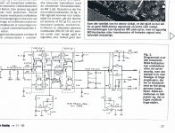
Only backside is that you have to have a very tight cabinet, to avoid light coming out of the cracks, when used in a dark room. I have used this mc stage since 92, where it was part of a danish diy project from a hifi magazine developed by Lars Clausen (LC).
I have often thought about playing around with IR diodes to replace the lightbulbs, but never got to the actual experiments.
I have often thought about playing around with IR diodes to replace the lightbulbs, but never got to the actual experiments.
- Status
- This old topic is closed. If you want to reopen this topic, contact a moderator using the "Report Post" button.
- Home
- Source & Line
- Analogue Source
- LC Audio Dual Mono RIAA - Light MC Headamp