hi , i need a very good schematic diagram for a MM preamplifier with split riaa for 5532 op-amp , can you help me?
"5532" and "good MM RIAA" won't happen at the same time. Bipolar OPs are not very good candidates for high Z sources like MMs.
Hello scafas,
take a look at Douglas Self's book "Small signal audio design". Everything you need is explained in there. And the NE5532 (or better 5534A for lower noise) is nearly perfect for MM RIAA. If you want higher noise, take a JFET OPamp.
take a look at Douglas Self's book "Small signal audio design". Everything you need is explained in there. And the NE5532 (or better 5534A for lower noise) is nearly perfect for MM RIAA. If you want higher noise, take a JFET OPamp.
Hi,
there have been many discussions about which circuit topology may suit a MM-Phonostage best.
The needed gain is within the range of a single gainstage featuring the equalizing parts within the feedback loop. Splitting the equalizer-parts more gain stages or additional buffers are needed. This additional effort may pay back by improved noise and thd-figures and maybe higher precision of the amplitude response. But this may be debatable point regarding the number of different preequalizing curves and the manufacturing process of vinyl.
If You decide for split Riaa the Q arises to which degree You split up.
Its a very good compromise to amplify linearly with a lownoise gainstage. A DC-Servo or 20Hz Highpass (Riaa/IEC) may already be integrated in this stage. A passive 2120Hz RC-filter may follow which may be designed for low losses and noise-performance (a RIAA-Neumann-EQ is optional here). Then a gainstage with active equing of 50/500Hz may follow.
With regard to flexibility, noise- and THD-performance such a topology would be hard to beat without considerably more build effort and cost.
The first gainstage could be a lownoise OPamp. Since a MM-pickup together with the typical 47kOhm input impedance resistor define the impedance range between ~2kOhm and 47kOhms the OPamp should have its noise minimum within this range. Above app. 2kOhms FET-Input OPamps show on par or better noise figures than bipolar Input OPamps. Still though Voltage noise figures should be ~5nV/sqrHZ or less. The current noise figures -which come into play whith rising impedance values- of FET OPamps are much better than those of bipolars. The OPA2130 of the Hagermann-circuit would be too noisy for my taste. Compare e.g. to the AD745.
Despite its age, the NE5532/5534 is not all that bad for MM stages and it surely wins on costs.
On first inspection of the Hagermann Bugle You can see that there are three linear gain stages, all of similar and lowish gain and fully passive equalization. For lownoise You usually design most of the required gain into the first stage. With most OPamps You can rise the supply voltages to +-15V which allows for more gain or gives You headroom. The fully passive eq requires more gain than a active or half-split passive-active eq and is as such inferior noisewise. The rising amplitude response of the input signal has to be taken into account especially when the first stage is a linear gain stage, because of the rising amplitude response of the Riaa preequalizing may drive the gainstage into clipping. The 2120Hz lowpass should therefore follow asap. The Bugle puts the 50/500Hz filter first, between U1 and U2. While this solves the problem of possible HF-overdive, it wastes precious gain between 50Hz and 2120Hz -->more noise. I´d rather interchange the position of those networks.
The function of R12, R11 and R9 remains unclear. They add noise and increase the impedance differences between the two OPamp inputs --> Offset issues. They may be omitted with. The third stage -if required anyway- should rather be a buffer than a gainstage, because two gain stages are already more than sufficient to achieve the required gain.
I´m missing some small bandwidth limiting caps in parallel to the feedback resistors R6, R4 and R2 to prevent the OPamps from oscillation and HF noise.
Here´s an alternative:
First stage´s gain is alot higher. AD745 is less noisy. Impedance imbalance is lower --> less offset. Csub may be omitted with and a DC-servo used instead.
R-values in 2120Hz network raised to allow for smaller C-values. Higher impedance of the network possible because of FET-Input OP2. OP2 may be a cheaper FET-OP like OPA132 et al with less stringent noise figures.
OP2s offset may be small , because of similar impedance values at its inputs.
OP2 serves as output buffer at the same. No additional active stage required.
jauu
Calvin
there have been many discussions about which circuit topology may suit a MM-Phonostage best.
The needed gain is within the range of a single gainstage featuring the equalizing parts within the feedback loop. Splitting the equalizer-parts more gain stages or additional buffers are needed. This additional effort may pay back by improved noise and thd-figures and maybe higher precision of the amplitude response. But this may be debatable point regarding the number of different preequalizing curves and the manufacturing process of vinyl.
If You decide for split Riaa the Q arises to which degree You split up.
Its a very good compromise to amplify linearly with a lownoise gainstage. A DC-Servo or 20Hz Highpass (Riaa/IEC) may already be integrated in this stage. A passive 2120Hz RC-filter may follow which may be designed for low losses and noise-performance (a RIAA-Neumann-EQ is optional here). Then a gainstage with active equing of 50/500Hz may follow.
With regard to flexibility, noise- and THD-performance such a topology would be hard to beat without considerably more build effort and cost.
The first gainstage could be a lownoise OPamp. Since a MM-pickup together with the typical 47kOhm input impedance resistor define the impedance range between ~2kOhm and 47kOhms the OPamp should have its noise minimum within this range. Above app. 2kOhms FET-Input OPamps show on par or better noise figures than bipolar Input OPamps. Still though Voltage noise figures should be ~5nV/sqrHZ or less. The current noise figures -which come into play whith rising impedance values- of FET OPamps are much better than those of bipolars. The OPA2130 of the Hagermann-circuit would be too noisy for my taste. Compare e.g. to the AD745.
Despite its age, the NE5532/5534 is not all that bad for MM stages and it surely wins on costs.
On first inspection of the Hagermann Bugle You can see that there are three linear gain stages, all of similar and lowish gain and fully passive equalization. For lownoise You usually design most of the required gain into the first stage. With most OPamps You can rise the supply voltages to +-15V which allows for more gain or gives You headroom. The fully passive eq requires more gain than a active or half-split passive-active eq and is as such inferior noisewise. The rising amplitude response of the input signal has to be taken into account especially when the first stage is a linear gain stage, because of the rising amplitude response of the Riaa preequalizing may drive the gainstage into clipping. The 2120Hz lowpass should therefore follow asap. The Bugle puts the 50/500Hz filter first, between U1 and U2. While this solves the problem of possible HF-overdive, it wastes precious gain between 50Hz and 2120Hz -->more noise. I´d rather interchange the position of those networks.
The function of R12, R11 and R9 remains unclear. They add noise and increase the impedance differences between the two OPamp inputs --> Offset issues. They may be omitted with. The third stage -if required anyway- should rather be a buffer than a gainstage, because two gain stages are already more than sufficient to achieve the required gain.
I´m missing some small bandwidth limiting caps in parallel to the feedback resistors R6, R4 and R2 to prevent the OPamps from oscillation and HF noise.
Here´s an alternative:
An externally hosted image should be here but it was not working when we last tested it.
First stage´s gain is alot higher. AD745 is less noisy. Impedance imbalance is lower --> less offset. Csub may be omitted with and a DC-servo used instead.
R-values in 2120Hz network raised to allow for smaller C-values. Higher impedance of the network possible because of FET-Input OP2. OP2 may be a cheaper FET-OP like OPA132 et al with less stringent noise figures.
OP2s offset may be small , because of similar impedance values at its inputs.
OP2 serves as output buffer at the same. No additional active stage required.
jauu
Calvin
Is RG not a little bit high for optimum noise ?
I like the structure that you do the 75usec first and then the rest active. That way the output opamp sees a signal with low slewrate. The falling response of the active stage keeps the available gain high at higher frequencies where the open loop bandwidth of the opamp falls off. The Baxandall solution is the other way around with passive 75usec and needs only one opamp when you you are happy with a rather high output impedance in the 600 Ohm range. I like your 2 stage design better.
I like the structure that you do the 75usec first and then the rest active. That way the output opamp sees a signal with low slewrate. The falling response of the active stage keeps the available gain high at higher frequencies where the open loop bandwidth of the opamp falls off. The Baxandall solution is the other way around with passive 75usec and needs only one opamp when you you are happy with a rather high output impedance in the 600 Ohm range. I like your 2 stage design better.
Hi,
thanks Joachim ;-)
With the AD745 RGs down to 1kOhm should be ok. Featuring a FET-Input the noise contribution of the OP wouldn´t change. Just the resistors inherent noise changes with different values of R.
On the other hand, I just hacked the thing into LTspice in a few minutes and thought, well 4k7 could just be about the impedance of the pickup in a middle frequency range. 😉 With similar impedances on the OPamps inputs the offset voltage contribution would remain small. FET input Opamps have typically higher specced input offset voltages, but with different source impedances and under highgain conditions the resulting output offset is considerably smaller. The much lower gain of the second stage is much less critical with regard to Offset. So there´s no urgent demand for a large DC-blocking cap at the output.
I like this structure, because it offers a lot of flexibility to accomodate for different pickups, not only by changing input load R and C but also the gain of the first stage. The passive 2120Hz filter then solves the problem of noninverting OP-stages that their gain can´t be lower than 1 (the Riaa asks for ever falling response-->gain=0).
If it were for the compactness of just one OPamp casing, a AD8620 could be an alternative to the AD745.
If a INA103 or INA163 is used for OP1 the circuit would be even more flexible. It could then be adopted for symmetrical inputs and could accommodate even for lowoutput MCs as in my original Calvin ( or PlatINA, or Clearaudio Balanced Ref. et al)
jauu
Calvin
You could also make a linear gain stage and the RIAA in the second stage shunt. That also holds precision over 20kHz but it inverts. The most simple solution is then to invert the cartridge pins, provided that the negative pin is not connected to the shield. That can give you more dynamic range in the treble because you burn aprox. 14dB @ 20kHz in the passive RIAA and it has no common mode distortion in the second stage. I would put the positive pin of the second stage on a servo, that gives you a floating ground.
take a look at the DH100, an old hafler design:
http://hafler.com/techsupport/pdf/DH-100_preamp_man.pdf
mlloyd1
http://hafler.com/techsupport/pdf/DH-100_preamp_man.pdf
mlloyd1
hi , i need a very good schematic diagram for a MM preamplifier with split riaa for 5532 op-amp , can you help me?
hafler dh100 started
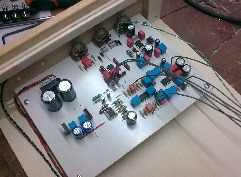
Hello everyone, I started to build Hafler DH100 clone.
and I 'left alone to build the section muting.
everything works perfectly and has a great sound.
before completing all, I saw that there are changes to improve the sound of the preamp, but I can not find detailed information on what to take.
Can you help me?
ok , good sound
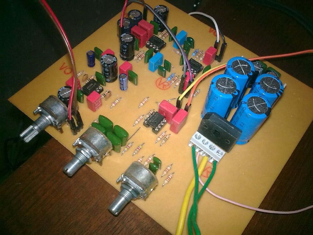
I switched the preamp yesterday and I must say that the first impression 'was very clean medium-high range.
control of tone and 'truly effective.
I am very satisfied.
assembly of the PCB and 'simple and everything worked the first try.
I switched the preamp yesterday and I must say that the first impression 'was very clean medium-high range.
control of tone and 'truly effective.
I am very satisfied.
assembly of the PCB and 'simple and everything worked the first try.
last definitive
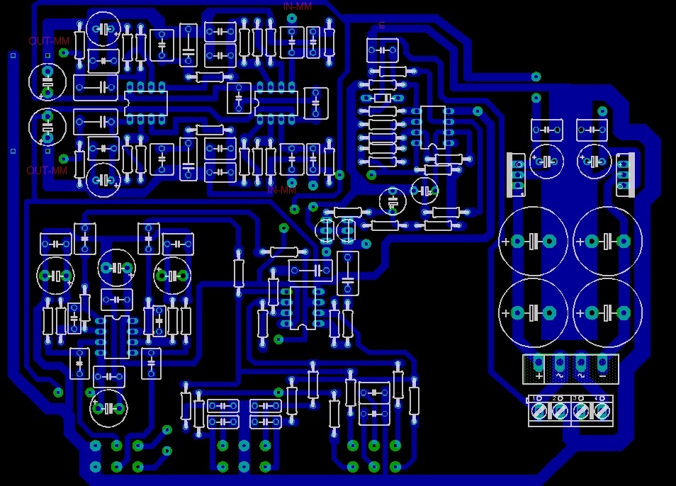
this is my definitive version of hafler dh100 clone.
the pcb does not include the mute stage.
I am very happy with the sound it.
this is my definitive version of hafler dh100 clone.
the pcb does not include the mute stage.
I am very happy with the sound it.
this is my definitive version of hafler dh100 clone.
the pcb does not include the mute stage.
I am very happy with the sound it.

Sorry for bringing this quote back up again in this thread - but I am curious to why this is the case. From what impedance would this be troublesome (seeing you can load your pre-amp with something lower than the standard 47K). The reason I'm asking is that -for example- the NE5532 has a lower noise floor than the OPA2134."5532" and "good MM RIAA" won't happen at the same time. Bipolar OPs are not very good candidates for high Z sources like MMs.
- Status
- Not open for further replies.
- Home
- Source & Line
- Analogue Source
- split riaa