This receiver works great............except for the tuner.
The tuner display and controls work, but have no effect on the output.
I get FM hiss and AM static, but no signals on either band.
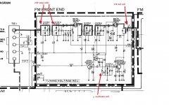
There is an exception: When I place my finger on pin 1 of IC201 (HA11225), I'm hearing 2 blended FM stations and they're from over 1000 miles away! The led power meter also activates when I do this. I've checked all around the board for correct voltage levels and they're good. Grounds are good too. Connectors are properly oriented. A complete visual inspection of the PC board under magnification turned up nothing special. I have the service manual and schematics, but the manual doesn't offer much help in troubleshooting and the schematic is rather tough to follow. There are several test points on the schematic, but I can't find any reference to them in the documentation. (please see the attached docs)
I'd really appreciate any help from anyone out there who's had some experience with HK tuner boards. Or maybe one of you might have an old board that needs a good home?
The tuner display and controls work, but have no effect on the output.
I get FM hiss and AM static, but no signals on either band.
There is an exception: When I place my finger on pin 1 of IC201 (HA11225), I'm hearing 2 blended FM stations and they're from over 1000 miles away! The led power meter also activates when I do this. I've checked all around the board for correct voltage levels and they're good. Grounds are good too. Connectors are properly oriented. A complete visual inspection of the PC board under magnification turned up nothing special. I have the service manual and schematics, but the manual doesn't offer much help in troubleshooting and the schematic is rather tough to follow. There are several test points on the schematic, but I can't find any reference to them in the documentation. (please see the attached docs)
I'd really appreciate any help from anyone out there who's had some experience with HK tuner boards. Or maybe one of you might have an old board that needs a good home?
I found the service manual ( google helped ") ). First you should check TP11 for voltage ( it should be between 1.5 and 2.3 volts and it should vary with the movement of the tuning knob - it's the control voltage for the variable capacitance diodes ). If that's ok you should try to adjust the oscillator coil ( first "tune" the receiver so the scale indicates a frequency of a strong local station ) and see if by adjusting the coil ( if it's an "air" coil - with no core - just press gently the turns of wire closer together or further apart until you hear ( possibly very faintly ) the station it's supposed to be tuned to. If it doesn't work some components - most likely the oscillator transistor - are defective. If it works adjust the rf amp coils and lastly the if coil for maximum sound.
). First you should check TP11 for voltage ( it should be between 1.5 and 2.3 volts and it should vary with the movement of the tuning knob - it's the control voltage for the variable capacitance diodes ). If that's ok you should try to adjust the oscillator coil ( first "tune" the receiver so the scale indicates a frequency of a strong local station ) and see if by adjusting the coil ( if it's an "air" coil - with no core - just press gently the turns of wire closer together or further apart until you hear ( possibly very faintly ) the station it's supposed to be tuned to. If it doesn't work some components - most likely the oscillator transistor - are defective. If it works adjust the rf amp coils and lastly the if coil for maximum sound.
All of the above is a somewhat crude approach but it doesn't require any specialized equipment . For a more technical and accurate method you would need a signal generator and an oscilloscope ( capable of handling signals in the 89-108 Mhz range ) and check all the components and adjust the coils.
). First you should check TP11 for voltage ( it should be between 1.5 and 2.3 volts and it should vary with the movement of the tuning knob - it's the control voltage for the variable capacitance diodes ). If that's ok you should try to adjust the oscillator coil ( first "tune" the receiver so the scale indicates a frequency of a strong local station ) and see if by adjusting the coil ( if it's an "air" coil - with no core - just press gently the turns of wire closer together or further apart until you hear ( possibly very faintly ) the station it's supposed to be tuned to. If it doesn't work some components - most likely the oscillator transistor - are defective. If it works adjust the rf amp coils and lastly the if coil for maximum sound.All of the above is a somewhat crude approach but it doesn't require any specialized equipment . For a more technical and accurate method you would need a signal generator and an oscilloscope ( capable of handling signals in the 89-108 Mhz range ) and check all the components and adjust the coils.
Attachments
Oops. Glad you found the schematic. The receiver doesn't pick up anything at all. Neither AM or FM. Even with a good antenna tuned to a local station. I can scroll up and down with the digital tuner, but it just picks up hissing, so I know a part of the tuner is still working. I'll follow your directions and see what I can find. I'm not very experience with RF circuits, but I do have a signal generator and a 200mhz scope, so perhaps you could guide me through the rest of troubleshooting.
The problem seems to be control circuit of the front end sections ( the PLL loop - IC701 - the prescaler, IC702 - the pll synthesizer ) and that's just a little bit out of my league. You could check those IC's ( and IC703 ) with a voltmeter to see if the voltages on the pins correspond to those in the schematic, maybe you can find the damaged one.
TP11 (vt) shows .016 volts. TP7 (fout) has a fixed high frequency signal and does not vary with the tuner settings.
The problem probably lies somewhere outside the rf front end. The tp11 should show a changing dc voltage when you tune the frequency on the control panel which in turn causes the frequency of the local osc signal at tp7 to change. Try applying a variable dc voltage at tp11 with a lab dc supply through a 1kohm resistor and see if you can tune in some stations, so as to rule out the frontend.
The fact that the rf frontend sends the local osc signal out indicates a digital PLL tuning control is employed. This system takes the local osc frequency (at tp7), counts it down and compares against an internal reference frequency, the error is then translated into the tuning voltage (tp11) to tune the local osc frequency. The same tuning voltage also tunes the rf input and amplifier circuit. Such system is usually part of a u-con. So what you want to check, after ruling out the rf frontend, is the circuit around the u-con, for example the pwm filter that generates the tuning voltage, its power supply, and so on.
Varying the voltage at TP11 did in fact tune in stations. So it appears that we can rule out the front end.
Now I'm having trouble understanding the next step. What is a U-con? Where is the PWM filer? It isn't identified on the schematic. There are a large amount of components in these areas, including several ICs, so I'd need some help in zeroing in the areas to check.
Now I'm having trouble understanding the next step. What is a U-con? Where is the PWM filer? It isn't identified on the schematic. There are a large amount of components in these areas, including several ICs, so I'd need some help in zeroing in the areas to check.
Here's some possibly useful info:
IC710/TD6104P
1-5.54V
2-5.49V
3-4.56V
4-0V
IC702/TC9147AP
4-4.74V
5, 22, 23, 24, 27, 28, 32, 33, 35, 36 - 0V
29-.015V
30-5.6V
34-.33V
40-5.05V
41, 42 - 4.95V
Now this one looks off:
IC 703/TD6301PA
1-0v
28-12.61v
Per the schematic, Pin 28 should read 5.5v.
IC710/TD6104P
1-5.54V
2-5.49V
3-4.56V
4-0V
IC702/TC9147AP
4-4.74V
5, 22, 23, 24, 27, 28, 32, 33, 35, 36 - 0V
29-.015V
30-5.6V
34-.33V
40-5.05V
41, 42 - 4.95V
Now this one looks off:
IC 703/TD6301PA
1-0v
28-12.61v
Per the schematic, Pin 28 should read 5.5v.
u-con = micro controller. I don't have the schematic and can't discuss in details. consumer electronics usually use cheap controllers that would not offer sufficient resolution at the DAC ports for tuning voltage, they often get away with an i/o port programmed as pwm working with an external power supply paired with an R-C LPF to obtain the resolution needed. Again without a schematic I can't tell there is such circuit in your receiver. Can you post the controller part of the schematic?
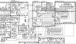
Look at the LPF block in the schematic, above the u-con IC702. If possible, disconnect the drain lead of Q702(or simply remove Q702), then measure and make sure the 30.0V supply is good. If 30.0V is confirmed good, try to replace C709 with a new one, preferably a film cap as opposed to an e-cap. watch the voltage rating of 50V or higher.
I pulled the FET and did not read 30v, or any voltage at all for that matter.
+44 volts should be feeding the bridge rectifier (D71) on the tuner board, which is then converted to 30 volts at Q75/Q76. This voltage is not present.
The voltage source on the main board is good, so the loss is somewhere in between. Again, the schematic is difficult to follow, so it may take a little while to find where the loss is occuring.
That's right. The 30.0V takes supply from the power amp positive rail (44.0V), through R82 as current protection, through in-rush limiting circuit Q75 an Q76, then stabilized by D75. all you need to do is an ohm measurement between the 30.0V line and GND making sure they don't short to each other, then checking up R82 Q75, Q76, D75(30v zener), and the resistor across b-e of Q76, as well as C74(the cap parallel to D75).
Easy fix.
Easy fix.
Last edited:
- Status
- This old topic is closed. If you want to reopen this topic, contact a moderator using the "Report Post" button.
- Home
- Source & Line
- Analogue Source
- Harman Kardon 690i Funky Tuner Board