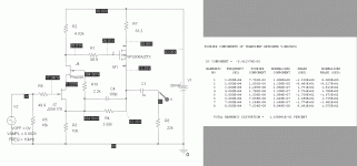
Attached is a schematic and response results for a gain cell using a cascoded N-channel jfet plus a p-channel small signal mosfet. There is feedback, but the feedback path is short and direct. The cell as shown is set up for a gain of 40x. Distortion results are impressive. I've laid out an RIAA preamp using a pair of these cells with a passive RIAA network in between, and will add it to the growing pile of things to be built/evaluated. By using the mosfet, you can use direct coupling between stages and still have some leeway to bias both stages properly.
Attachments
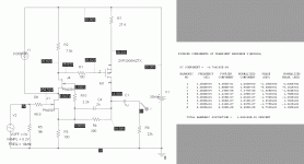
Here's a ~5X lineamp based on a similar cell structure, but with a "helper" current source for the input jfet, my old friend the PN4391. Food for thought...
You could also do a low level gain cell with the BF862 in front end duty with a helper source. I haven't characterized my little roll of BF862s yet (lazy, I guess), so I don't know how much help they'll actually need.
You could also do a low level gain cell with the BF862 in front end duty with a helper source. I haven't characterized my little roll of BF862s yet (lazy, I guess), so I don't know how much help they'll actually need.
Attachments
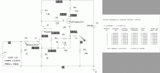
Here is a low level sim using the BF861, which has a model in PSpice. Gain is 30X (needs tweaking), but distortion is nice, so similarly fruitful result could probably be expected for cousin BF862. If someone wants to take this schematic and tweak it with an available BF862 model, I'm sure the results would be interesting to more than myself.
Attachments
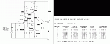
As promised quite a while back, here is the basic gain cell configured so it will run with a Darlington. To get this to work, I used the equivalent of 3 X GaP green LEDs (2V each, ~ 13 ohms incremental impedance if you use the HP variety) in the emitter of the Darlington (6V+ 39 ohms equiv. resistance). I also put a current source from the Darlington collector to ground so I could run some extra bias current through the Darlington + LEDs and still get reasonable output voltage centering. It'll be interesting one day to look at the actual THD and harmonic distribution vs. the sim.
Another beast for the menagerie.
Another beast for the menagerie.
Attachments
This is true, but getting them to work in the current version of PSpice is a royal pain in just about every nether part you can imagine. Maybe I should give LTSpice a try or unearth and upgrade my copy of Beige Bag Spice ( or just buckle down and figure out how to work with PSpice). There are models from IXYS and Supertex (their depletion-mode stuff) I'd like to be working with as well...
Actually this looks like a "double" cacode to me - you have drawn a folded cascode where the the bottom (nFET) device is itself a cascode of 2 nFETs.Attached is a schematic and response results for a gain cell using a cascoded N-channel jfet plus a p-channel small signal mosfet. There is feedback, but the feedback path is short and direct. The cell as shown is set up for a gain of 40x. Distortion results are impressive. I've laid out an RIAA preamp using a pair of these cells with a passive RIAA network in between, and will add it to the growing pile of things to be built/evaluated. By using the mosfet, you can use direct coupling between stages and still have some leeway to bias both stages properly.
A simple folded cascode (1 nFET, one pFET) will give the normal cascode benefits of reduced Miller capacitance and also provide the DC level shifting, is there any reason to add complexity? ie it appears to me that the additional nFET is not required, can you please explain rationale for adding this in?
These are all complementary feedback pairs of some sort, with cascode on the input stage (not totally necessary in some cases) to reduce the effect of the miller capacitance on the first stage - certainly a concern if used as the first stage of an RIAA preamp - maybe not for other applications.I have looked at simulations where I've use a folded cascode (not in this thread, I don't post everything I do by a long shot). This is possibly an option for the first stage of an RIAA preamp where the signal amplitude is small, but not for a second stage or a low gain line amp where the signal/current swing is higher. If you differ, please posit a circuit as an example, and we can talk about it.
The basic premise of what has been presented here is a complementary pair where the excess gain is fed back to reduce overall distortion - all the other little bows and ribbons are secondary to that purpose. I have another thread where the two sections of the circuit are AC coupled to allow independent bias of input and output stages - the important concept here is DC coupling between input and output stage along with decent biasing/centering and good overall THD.
The basic premise of what has been presented here is a complementary pair where the excess gain is fed back to reduce overall distortion - all the other little bows and ribbons are secondary to that purpose. I have another thread where the two sections of the circuit are AC coupled to allow independent bias of input and output stages - the important concept here is DC coupling between input and output stage along with decent biasing/centering and good overall THD.
Sorry my mistake - this is not a folded cascode as I mistakenly stated in my previous post it is a cascade - input to the p-channel fet is via the gate not the source. Ignore me.These are all complementary feedback pairs of some sort, with cascode on the input stage (not totally necessary in some cases) to reduce the effect of the miller capacitance on the first stage - certainly a concern if used as the first stage of an RIAA preamp - maybe not for other applications.I have looked at simulations where I've use a folded cascode (not in this thread, I don't post everything I do by a long shot). This is possibly an option for the first stage of an RIAA preamp where the signal amplitude is small, but not for a second stage or a low gain line amp where the signal/current swing is higher. If you differ, please posit a circuit as an example, and we can talk about it.
The basic premise of what has been presented here is a complementary pair where the excess gain is fed back to reduce overall distortion - all the other little bows and ribbons are secondary to that purpose. I have another thread where the two sections of the circuit are AC coupled to allow independent bias of input and output stages - the important concept here is DC coupling between input and output stage along with decent biasing/centering and good overall THD.
The harmonic distribution on the last circuit I posted in #5 bugs me - the overall THD is low, but there are a lot of high-order products that approach the 2nd in amplitude. I'm going to try tinkering with the current distribution between the input and output stages to see if I can clean it up some. The BF861 circuit looks much better from that perspective, for example, even though the THD is a bit higher..
Having said that, it'll be interesting to see how some of these circuits actually measure up.
Having said that, it'll be interesting to see how some of these circuits actually measure up.
Interesting! I've been simulating a similar circuit lately, but I have tried a different approach: the usual compound pair with a jfet input and a Sziklai bjt pair in the role of the PNP transistor (with the goal of achieving more gain). In my circuit the jfet doesn't add gain. In your circuit you have two summing gains: the cascode and the mosfet (with the feedback taming gain and distortion, and lowering the output impedance).
My idea was to use the circuit in a phono stage, with a passive filter between two stages. Did you develope your idea or was it a dead end street? How about using the feedback path for active equalisation split in two stages?
My idea was to use the circuit in a phono stage, with a passive filter between two stages. Did you develope your idea or was it a dead end street? How about using the feedback path for active equalisation split in two stages?
I have a full blown passive RIAA preamp using the descendant of this gain cell. I added some extra twists to increase the open loop gain and lower distortion. Subsequent evolution is described in this thread -
All-In-One Preamp Circuit
All-In-One Preamp Circuit
Last edited:
- Status
- This old topic is closed. If you want to reopen this topic, contact a moderator using the "Report Post" button.
- Home
- Source & Line
- Analogue Source
- Jfet-Mosfet Gain Cell


