These are the very cheap stepper motors I found in the PDF . Years ago I found another link to someone who had converted similar ones to AC ( now it's lost ) . When I wrote to him he said it is no big deal and just needs a capacitor to make it work . One might guess 4.7 uF ? I have no idea exactly where this would go . The construction of the motors looks identical to the over priced turntable versions . Seems worth trying ? Conventional DC stepper drive I suspect is no worse ? There is no magic about motors like this . To be honest none are really right for a turntable . The AC hysteresis type is better . These are rare . I made my own for 501 ( stock parts converted from a centrifuge motor , 30 % not used ) . It had a 28 W rating .
The strange part about a hysteresis motor is the phase shift is by a magnetic distortion created by short circuited turns of copper ( shaded pole ) . This is not the 90 degrees it might ideally be . It is less . However the way the rotor follows the circulating magnetic field with a slip angle greatly helps . When loaded it is like an elastic link pulling things along . A stepper fights all the way which never allows the motor to be part of a damped system ( the belt can do that , usually too well ) . The vibration of a hysteresis motor is high , however it is often lower than a stepper of a given power . A bit like saying a V8 is better than a single cylinder engine whilst not being a turbine . V8 will do nicely . I don't say straight 12 as I suspect we don't get that far . Multi-motor might if mechanically timed and joined do some of that . That is not as difficult as it might sound .The motors almost by the way they are made will self align . Just using the lead out wires as a timing reference probably will be good enough . The motors automatically jump to a pole position .
http://www.rapidonline.com/pdf/37-0507.pdf
http://www.rapidonline.com/Electric...507/?sid=d20c0abb-7cff-4710-8ce8-5d7ffd919ca0
http://www.cas.mcmaster.ca/~lawford/3TB4/ref/Stepper.pdf
Last edited:
This is the text I found before . There is much to commend in his turntable . The motorcycle valve is a good idea . Motors also .
The Altmann DIY Turntable
The Altmann DIY Turntable
There are a few ? Nottingham Analogue I believe ? The point is as the sine wave enters the magnetic circuit it becomes squared . Thus a synchronous motor is just a stepper working at 50 at 60 Hz . Steppers have a resonant frequency which is best avoided . 50 or 60 Hz I suspect is an easy frequency for a stepper . The stepper if so is a very cheap source of a good motor . The one I gave as an example will work up to 0.5 A approximately ( at 12 V / phase ) . That looks to be more powerful than many . There is scope to play with the power verses vibration if so . My guess is 8 V rms will drive it if a sine wave . Also one can try a different frequency . A triangle wave might work well ?
It might even work from a NE555 timer if discharge transistor is connected to output . That gives up to 400 mA .
It might even work from a NE555 timer if discharge transistor is connected to output . That gives up to 400 mA .
Here is the big Crouzet synchronous . About 11 watts , used by Avid I believe ? This is typical of all synchronous I have taken apart . Not shown is a spring and nylon thrust washer which often is noisy ( bottom of the motor ) . If you notice the phasing is just the shaped metal triangles . The coils are very simple . If you beak open a motor you often can join it using standard solder and plumbers flux . The iron has to be very hot and the zinc filled off . As my brother proved many times steel will just about solder . The advantage is not so hot as to cause problems and will retain any adjustments .

Last edited:

I didn't want to leave this thread without an answer to a question I posed . Can a stepper motor make a good synchronous motor ? I bought one of the motors from Rapid . Less that one hour later I had all the answers I needed . The simple answer is yes it does make a nice motor . I only used a holding it and voltage meter test ( equal voltages seem to indicate phase shift about right usually ) . As far as I can tell at 6V rms 12 uF is ideal ( 10 uF used ) . 12 uF was a pleasant surprise as it not too expensive . The transformer I list is what was in my useful box . I suspect the ideal transformer would be 12 V 6 VA . I would use a series resistor into the primary side to drop the output to < 11 V rms . I would do it to the primary so as to lower waveform distortion . Cheap transformers are bad on that . A light bulb might do well ( 15 W ? ) . Consumption is about 100 mA x 2 at 8V 50 Hz ( slightly less than expected , almost a clone of the famous Airpax I list ) . I calculated 78 Hz as the point where I expect the performance to drop if going the electronic route using a Quadrature oscillator and power amp . I would imagine LM324 ( MC33079 ) and 2 x BD135 and 2 x BD136 to be workable . It is possible that no heat sinks would be required . Thoren's used un-biased class B for the TD125 . If a 51R feed forward resistor was used I suspect distrotion would be low . 78 Hz is the the calculated for a steeper on square waves ( 390 RPM ) . It should work better on sine waves and might go higher .
http://www.daycounter.com/Calculators/Stepper-Motor-Calculator.phtml
From what I can tell this motor is very much like this ( old Airpax = LP12 ) .
Buy AC Motors Record deck synch motor,250rpm 110V McLennan Servo Supplies 9904 111 31813 online from RS for next day delivery. ( plus £11 tax )
Chassis Transformer 230V 6VA 12V+12V
12uf Plastic Case Motor Run Capacitor
http://www.rapidonline.com/Electric...507/?sid=d20c0abb-7cff-4710-8ce8-5d7ffd919ca0
The 12 uF is a bit OTT . Any film type will do .
Last edited:

Here is a quadrature oscillator . Change the 22/10M resistors . I used an LM 324 . It gives very good performance all things considered . The chip shown needs 30 pF compensation caps , not so LM324 . I did try to make a simple power amp to drive the motor with the spare sections . That was less happy . A gain of about 30 for each of the power amps ( TDA 2040 ? ) . The distortion is remarkably good for such a simple circuit . I used 47 K where is says 50 K . Notice I was not close to 50 Hz . It needs tweaking to get right . The impedance of the chip makes a difference . TL074 might be closer to the calculated values .
I tried out the primary size resistor . 10 K does it well ( 2 W 500 V ) . The waveform looks none too special . Gives about 7.5 V if so . This 9V one gives nearly 11.5 V at this load in the UK .
In a rush now so forgive typo's .
Interesting stuff, Nigel. What about a Bubba Oscillator? Is it over-kill or not work in this application?
Bubba Oscillator | Simple Circuit Diagram
Thanks for your work so far.
Vince
Bubba Oscillator | Simple Circuit Diagram
Thanks for your work so far.
Vince

High Vince . I used a version of the Bubba called a State Variable Filter for the Garrard 501 . The ESP site shows something very similar . 91K and 10K resistors cancel the third harmonic . That will give about - 66 dB distortion . I was very impressed by the simple Quadrature above as it is giving - 57.5 dB . This is not a simulation . That is so close to zero as to be not worth talking about . The limiter is 2 x 1N4148 side by side rather than back to back as the diagram for two zener diodes . The low output is not a problem as the power amp can have the gain required . The . 57.5 dB is even more impressive as LM324 ( LM 358 dual package ) is not the stuff of dreams . The mains electricity is seldom better than -35 dB .
I made one error in building my oscillator . I used all 220K resistors . The one where the 10 M is shown should be lower than 220K . Useful to know that it still works as theory says it needs to be less . That is the place where adjustment is possible to trim frequency I suspect .
ESP - Sinewaves
I retested the motor . Note how at 245 V rms I get 12 V rms from what says is a 9 V transformer . 9V is at full load on 230 V . 51 R seems to be about right as a dropper .
I think using multiple 4.7 uF is a good choice as fine tuning is possible . Also a much better price . I noted excellent vibration using 10 uF . 20 uF gave more torque and more equal voltages , it also had more vibration . I suspect if using 20 uf the voltage could be dropped further . I have redrawn the transformer so as to stress that only a single winding is required . The voltage difference is typical of the LP12 ( 100 / 90 V Valhalla PSU )
4.7uf 250v 10% Metal. Poly Capacitor

This is a real test of the circuit above at the motor as it rotates . The main thing to note is the wave is still noticeably a sine wave . The 3rd harmonic distortion is > 10 % . As disgusting as it looks it is the right side of OK . 3 rd harmonic is bad news because it works against the rotation , a prime source of vibration . The Garrard 501 was about - 55 db all distortion added together including the motor itself . If I had rewound the motor to 25 V rms I could have realized - 66 dB . 11 dB was the output transformer . The good news here is we don't need an output transformer if using a small power amp . 8 V rms is about the output of an op amp . L165 might be ideal ( TDA2030/40/50 also , same PCB I think should work )
Buy Operational Amplifiers Single power op-amp,L165V TO220-5b Magnatec L165V online from RS for next day delivery.
Buy Audio Amplifier Printed Circuit Boards TDA2030 PCB audioamplifier,10W 79x63.5mm One Way Circuits M12653 online from RS for next day delivery.
Last edited:

I realized I had a TDA 2040 already soldered up into the RS PCB listed above . Running both phases I feel more than proves it to be workable . BTW ,This is real . Note how low the distortion of TDA2040 is although close to clipping ( it is almost the same as the input signal ) . The TDA 2040 is used in the standard PDF circuit . I see no reason to think TDA 2030 would be much different . I have seen it recommended as a stepper driver . TDA 2030 often sells for about $1.50 . I used the very cheapest clip on heat sink . The PSU need not be expensive . The signal generator used here is a bog standard schools type . Note it is not as good as the Quadrature oscillator . Note also the Quadrature oscillator would drive these amps directly if using 2 x 1N4148 limiters . If anyone didn't understand , the orange phase using cosine and the brown the sine output . Reversing the colours reverses the rotation .
I retained the resistors as I felt it helped a little . If in bi phase I imagine it might be better without them ?
Running seemed to be possible from 12 Hz to as much as 95 Hz . 12 Hz was useful as it gives a 1 second rotation which says that it is 250 RPM @ 50 Hz . That could be useful . If the platter is 300 mm that would allow the pulley to be 30 mm . That will just about allow 45 RPM at the maximum speed of the motor . The calculated maximum for the stepper is 78 Hz . My tests seem to confirm that to be the peak . However as theory says a sine wave will allow slightly more . If you use 40 Hz for 33 1/3 then 78 RPM should be possible . I think that would be very OK . From memory the Airpax motor used by Linn was slightly less obliging . It seemed to peak at 70Hz . Also the torque of this motor seems better . It doesn't get hot either which was not true of the Airpax ( no harm as it is designed to cope ) .
Note the motor still plays it's tricks with the wave . If the resistor was zero ohms it would be interesting to see what effect it has . It sort of says Linn were being a bit imaginative to say what they did about the Lingo . What we have here I suspect is starting to outperform that ? If we shop carefully we will not spend $40 total .
That would be great if someone is brave enough to take it to the next step . I have to admit I had a miserable week of hard design problems at work ( still to be fixed ) . Giving 2 hours to this has been fun . A famous manufacturer who sells turntable upgrade kits asked me to show him how to do this . At no point did he mention money so I felt to say the least abused . This is fairly typical of our industry . Also not one of the professors of turntables knew how to do it . 2 hours from concept to reality , shame on you professors of audio .
This design should be universal . If I had a 1.8 degrees stepper it would have been fun to see where that went . As a rule of thumb the DC x 0.7 is the AC required ( maximum , I would say 0.5 A maximum design current as a guide ) . I have been getting great results at 4 V rms . An interesting thing . The coil resistance is 25R . If it was the dominant part of the impedance the voltage would be split differently . As the voltage is 2/3 Motor 1/3 resistor it shows significant inductance . That is no bad thing as it will not require anything special from the TDA2030 . It also reduces current down to 80mA per phase . I think keeping TDA 2030 up at 10 V rms and adjusting the motor with resistors has much to recommended it . However direct coupling with the oscillator output adjusted might be preferable ? TDA 2030 is +/- 22 V , that is in it's favour .
Buy Audio Amplifier ICs Audio Amp Speaker 1-CH Mono 18W Class-AB STMicroelectronics TDA2030AV online from RS for next day delivery.
Stepper Motor 35x28mm 10V 500mA
The motor I choose looked closest to the usual Airpax types . One thing to consider is the frequency of vibration produced . Hard to say what is ideal . I suspect > 8Hz is more problematic ( 480 RPM) . That by coincidence is the limit of this motor .
If I get a moment I will build a tidy version of the Quadrature oscillator . The one I built is a mess .
I have to say the Airpax ( sold under many names , Originally Philips Belgium ) is as un-special as it is possible to get . The simple fact is it is about right as a compromise . To say it is well made or precision shows the person has not looked very far at other designs .
I suspect the first Steppers were adapted Synchronous motors ?
Last edited:
I just did one more test . I am not happy with 40 Hz / 200 RPM , it is noticeably less good . When the motor is warm 117 Hz / 585 RPM is OK . That gives 78 RPM . The vibration is excellent . Surprisingly voltage has not dropped via the 51 R at 117 Hz , therefore 2PiFL ( inductance ) is not the whole story . Induction motors that run happily at 130 V 50 Hz need 230 V at 117 Hz . The torque is less at 117 Hz with this motor ( 120 Hz max ) , probably enough to offer the chance to play 78's . The peak torque does seem to come at 78 Hz 390 RPM as predicted by the maths . 50 Hz is fine . This proves to me that the 7.5 degrees stepper is a 50/60 Hz synchronous . My instinct is to say just like transformers iron is happier at 55Hz . It probably is OK to use a higher voltage on 117Hz . My guess is 9V rms would be fine at the coils .
I would guess that the true bi phase ( 2 TDA 2030 ) might just work a little bit better and might go faster .
The heat-sink is about as hot as is wise . In bi phase it would be less .
TO220 Heat sink clip or screw mounting
I would guess that the true bi phase ( 2 TDA 2030 ) might just work a little bit better and might go faster .
The heat-sink is about as hot as is wise . In bi phase it would be less .
TO220 Heat sink clip or screw mounting
Nigel, one quick question. I don't want to disrupt your momentum, but maybe you can help.
I just received a 50w T-amp. When connecting a stepper motor to the output of an amp, which motor leads go to the amp channel positive and negative? Is it connected across the coils or does it depend on the motor? The wiring on a Hurst motor I have, opposite coils are joined. The stepper motor is a 7.5 degree Portescap.
Also, does it matter which motor coil is connected to the channel with the leading 60 Hz, 90 degree signal?
I would experiment, but its a new amp. I'd hate to fry it so soon.")
Thanks
Vince
I just received a 50w T-amp. When connecting a stepper motor to the output of an amp, which motor leads go to the amp channel positive and negative? Is it connected across the coils or does it depend on the motor? The wiring on a Hurst motor I have, opposite coils are joined. The stepper motor is a 7.5 degree Portescap.
Also, does it matter which motor coil is connected to the channel with the leading 60 Hz, 90 degree signal?
I would experiment, but its a new amp. I'd hate to fry it so soon.
Thanks
Vince
Last edited:
I have some Pabst 2 pole hysteresis motors. they run 1500 rev/min om 50 Hz 24V. I'am considering to make a sine wave generator and make the phase shift as per suggested here. but i realize that you're take on the stepper motor just may be the better option.
Off-course the Pabst motor has the benefit for the construction with the heavy outside rotor, but that can be done on the steppers also with a fly wheel design.
A really nice design would have 3 groups of 2sine/cosine, each driving a motor that then in turn drives a flywheel. A bit of a design work I guess..
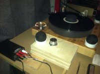
Here's my setup with a stepper motor. Has a bit less vibration than the 115v cap driven motor. There's a bit more bass and its picking up more detail.
Only tried a 60hz tone. Haven't put a strob on it yet either.
Not bad for a $4 motor. Still have two motors as backups.
Only tried a 60hz tone. Haven't put a strob on it yet either.
Not bad for a $4 motor. Still have two motors as backups.
Attachments
Nigel, one quick question. I don't want to disrupt your momentum, but maybe you can help.
I just received a 50w T-amp. When connecting a stepper motor to the output of an amp, which motor leads go to the amp channel positive and negative? Is it connected across the coils or does it depend on the motor? The wiring on a Hurst motor I have, opposite coils are joined. The stepper motor is a 7.5 degree Portescap.
Also, does it matter which motor coil is connected to the channel with the leading 60 Hz, 90 degree signal?
I would experiment, but its a new amp. I'd hate to fry it so soon.
Thanks
Vince
Do what I did . Take the DC voltage , call the AC 0.7 of that voltage . I dare say a slightly higher voltage will be OK , however 0.7 seems fine as a starting point . Next get an ohm meter to find the coil pairs and verify coil resistance ( 25 R if my example ) . Buy the cheapest transformer of the right voltage . I would say for similar to mine 12 V 12 VA as it can be used to drive little power amps later ( assume TDA2030 to be 50% efficient , thus 12VA ) . Use something like 50 R to the 0 V so as to limit current . Use 2 x 4u7 caps ( 9.4 uF ) as that is likely to work regardless of the value eventually found to be correct . By playing around the connections are found . Use a couple or 50R to the two coil ends ( 2 x 100 R 0.6W ) . For absolute safety use 100 R if 12/15 V . When all is working test the voltage dropped across the resistors . Calculate the current used . Remember it is times 2 . If only 2 watts used by the motor there is a good chance 12 V 6 VA will be OK via power amps . 12 V ( x 2 ) on a cheap transformer will give about 16 VDC for most counties . That will just about give 8 V rms from little amps . 15 V ( x 2 ) is a bit risky as 23 VDC might be seen . If so a few 1N 4007 ( always buy the high voltage ones as they will do a thousand jobs ) will cheaply drop the voltage ( 0.8V / diode approx ) . Swings and roundabouts . It is nice to have the highest voltage .
I prefer my little chip amps as they seem ideal for the job . If people buy the little PCB then RS will make a new batch . Such a good price . I think RS is around the world ?
A spare stereo amp would be a way to drive it . I see them at car boot ( trunk ? ) sales . How cool would it be to have a NAD 3020 driving the turntable . If very clever use it's phono side at the same time ( NAD has split power/pre amp ) ? As the current used is small it probably wouldn't corrupt the sound . Put in a small PSU for the 3020 pre amp . Now that starts to look very interesting .
Use 2 x 100 R on start up with power amp . Gradually use lower values until the torque seems good . On mine even at 4 V it was difficult to stop by squeezing thumb and finger around it . From memory the Linn / Lingo had less torque on the 66V setting ( higher start current using up to 115 V for that motor ) . If you want start up boost use a NE555 and relay . For 78's I guess full voltage , the relay overridden .
TDA2030A Amplifier Amp board DIY kit BTL/OCL TDA2030 | eBay
Last edited:
I have some Pabst 2 pole hysteresis motors. they run 1500 rev/min om 50 Hz 24V. I am considering to make a sine wave generator and make the phase shift as per suggested here. but i realize that you're take on the stepper motor just may be the better option.
Off-course the Pabst motor has the benefit for the construction with the heavy outside rotor, but that can be done on the steppers also with a fly wheel design.
A really nice design would have 3 groups of 2sine/cosine, each driving a motor that then in turn drives a flywheel. A bit of a design work I guess..
The Pabst deserves low distortion much more than a stepper/synchronous . Here is the concept of one I made for Pabst . It's owner wanted to retain the 22 uF . As he was very frightened of the motor being damaged I put in a 100 uF non polar cap to protect it ( could be larger ) . The last section was a power amp that would give 100 watts 8 R ( and why not ) . It was configured as a linear phase filter ( not shown ) . Again why not as a power amp usually looks exactly like an op amp . The design was longtail pair input 8 mA VAS ( 47 pF ) CCS and TO3 Darlingtons ( 2 x 0R33 ) . The Bias a single LED ( that's OK for a motor and shows it is working , no crossover distortion when only 50 Hz ) .
If doing it again I would use some 100 watt chip amps ( TDA 7293 ? for 25 V rms out ) and the Quadrature oscillator . If they power amps I show are configured as an active filter the - 57 db distrotion of the oscillator could be very cheaply improved . Always a bit risky , mine was OK .

Here's my setup with a stepper motor. Has a bit less vibration than the 115v cap driven motor. There's a bit more bass and its picking up more detail.
Only tried a 60hz tone. Haven't put a strob on it yet either.
Not bad for a $4 motor. Still have two motors as backups.
GOOD . The turntable looks like something I want to build . My girlfriend bought me a load of vinyl . I somehow don't want to use the LP 12 nor Garrard anymore . What I want to try is the bearing and platter of the Garrard 501 ( it has two slots for damper rings , ideal as a drive slot ) . I am even thinking of a 0.9 ( or 1.8 ) degrees stepper running at 33 1/3 RPM . 2 x 501 platters joined by a cord . 2 x Garrard 301 work very well that way . The stepper would drive one platter directly . It would probably need a push start ?
- Status
- This old topic is closed. If you want to reopen this topic, contact a moderator using the "Report Post" button.
- Home
- Source & Line
- Analogue Source
- motor and circuit for diy turntable project