Hi all.
After prowling around DIYAudio for sometime (and learning quite a bit...thank you) I've decide to post my own dilemma.
A bit of background.
Recently I purchased an old McCurdy phono pre (vintage 70's, possibly early 80's). The design is such that there is a single power supply feeding two independent Left and right circuit boards. The issue that I'm having is signal bleeding from one of the boards to the other. It doesn't happen the other way though. Because of the units age and the signal bleed issue I thought that I'd replace the caps as a make work project on my McCurdy guinea pig.
Each channel has:
2x Nichicon 330uf, 35v Radials
2x Nichicon H7648L 22uf, 35v Radials
1x Siemens 220uf, 63v (Brazilian made) Axial
1x Siemens 100uf, 63v (Brazilian made) Axial
1x Philips 030K0 10uf, 63v Axial
1x Siemens 47uf, 35v (Brazilian made) Axial
under a shielded housing (for the RCA jack, gain & Hi Freq Trim) are:
1x Philips 030K0 10uf, 63v Axial
1x Philips 47uf, 63v Axial
My thoughts.
Options that I found for replacing the axials are:
Vishay BC AML 138
or
Nichicon VX.
And, due to lead spacing on the circuit board, replacing the radials seems to come down to:
Elna Silmic 2
Nichicon ES
Nichicon PX
Questions:
Given two different caps are rated exactly the same, does physical size play any part in longevity, sonics etc...
The original 220/63 & 100/63 have tolerances of -10/+50%. The Vishay and Nichicon have +-20%. Will I be fine with my selection or do I need to find the original tolerances?
Can a cap 330/35 be replaced with a 470/35 or a 330/50?
The Nichicon PX is rated for a very long life, low impedance and a high ripple rating. The Elna's, not as much. Is there a real difference when the parts are in a personal phono stage? Can you get 10, 15 or 20 years out of Elna's?
Whew, that's it for now.
Any suggestions would be greatly appreciated.
Thanks,
Mitch
Dumb question- how have you determined that the signal bleed is through the power supply?
A schematic will help for parts recommendations- different caps have different ESRs and a supply with regulator X can be unhappy with caps that are perfect for regulator Y, and both are a different pot of pisces than an unregulated supply. Caps for the raw supply filter will have different requirements than caps to bypass voltage references. And so on and on.
A schematic will help for parts recommendations- different caps have different ESRs and a supply with regulator X can be unhappy with caps that are perfect for regulator Y, and both are a different pot of pisces than an unregulated supply. Caps for the raw supply filter will have different requirements than caps to bypass voltage references. And so on and on.
different caps have different ESRs
Hi Sy,
the phono stage is from the 70ies/early 80ies...any standard cap from today will be something like ultra low ESR in comparison to what was standard back then.
Any case, a schematic would be nice
")
I doubt the signal bleeding comes from the caps, while it certainly will not hurt replacing them. In my experience the caps are almost never a real issue for small signal analog circuits, even when 30 years old. It matters a bit more for PLL-circuits (turntables), though.
Change the caps, it's fun
just take care to not overheat the pads. For the old paper boards that quickly means a mess.Hannes
Last edited:
Hi Sy & h_a.
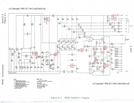
Well I finally got a scan of the schematic. I hope posting a companies schematic is not a problem.
I've circled all of the electrolytic caps that I'm looking at replacing. The schematic is for a single channel. The two channels sit above a single power supply. Since the channels are discreet (as far as I can tell) I speculated that somehow signal was getting to the other channel via the power supply.
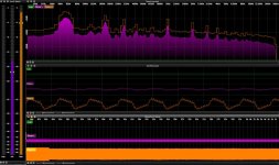
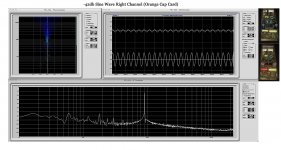
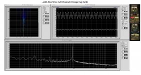
Also, I've uploaded a screen shot of my 1k sine wave test tone@-44db that I ran into the right channel (Orange) only. The left channel (purple) activity is some how related to the right channel signal. If I play the test tone in the left channel, the right channel is silent and shows no activity. As you can see there are issues. In the middle graph (Oscilloscope) the purple line should be flat like the green line and the orange line should be a SINE WAVE!
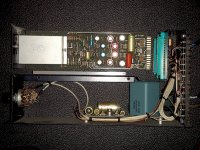
I thought that I'd post a picture of the general layout of the unit. For the pic it's laying on it's side.
Just to complicate things, is it possible to make the RIAA circuit more accurate? The specs claim RIAA +-0.5% Frequency Response from 30Hz to 15Khz. Can +-0.2% be achieved?
Well I finally got a scan of the schematic. I hope posting a companies schematic is not a problem.
I've circled all of the electrolytic caps that I'm looking at replacing. The schematic is for a single channel. The two channels sit above a single power supply. Since the channels are discreet (as far as I can tell) I speculated
that somehow signal was getting to the other channel via the power supply.Also, I've uploaded a screen shot of my 1k sine wave test tone@-44db that I ran into the right channel (Orange) only. The left channel (purple) activity is some how related to the right channel signal. If I play the test tone in the left channel, the right channel is silent and shows no activity. As you can see there are issues. In the middle graph (Oscilloscope) the purple line should be flat like the green line and the orange line should be a SINE WAVE!
I thought that I'd post a picture of the general layout of the unit. For the pic it's laying on it's side.
Just to complicate things, is it possible to make the RIAA circuit more accurate? The specs claim RIAA +-0.5% Frequency Response from 30Hz to 15Khz. Can +-0.2% be achieved?
Attachments
Hi,
the lack of scales makes things hard to understand; I guess you refer the -44db to 2V, so your input signal is about 12mV which should be fine.
From the looks of your amp it is from the late 80ies or so as it uses a fiberglass pcb, not paper. This somehow doesn't well connect to your schematic saying copyright 1996-2011?
Any case, please upload somewhere a larger schematic, this is almost impossible to read
Hannes
> schematic saying copyright 1996-2011?
The copyright notice is clearly digitally-stamped over a much older blueprint.
The era is 1970s, though this is conservative broadcast stuff and may have been in production well into the 1980s.
I've never seen broadcast stuff with paper boards. My 1970 RCA had glass-base boards which could have served as armor-plate. My LPB console had a lower grade of board but not the cheezy paper found in consumer junque.
The "signal bleed" is NOT on the boards, since these are one-channel boards with excellent supply rejection. Much more likely in external wiring.
> The specs claim RIAA +-0.5% Frequency Response from 30Hz to 15Khz. Can +-0.2% be achieved?
0.5% is 0.0433db error. This can be a VERY accurate RIAA. There are multiple options to screw it up for more punchy sound or to roll-off scratchy highs.
PRR is absolutely correct. I added the copyright, which I got from their web site, just to add clarity of ownership. The manual that the schematic comes from is dated April 1978.
"RIAA +-0.5% Frequency Response from 30Hz to 15Khz. Can +-0.2% be achieved?" is actually supposed to say "RIAA +-0.5db Frequency Response from 30Hz to 15Khz. Can +-0.2db be achieved?"
The reason I thought the problem was in the one of the boards was because if the boards were switched, the problem followed the one board.
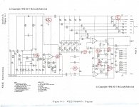
I've posted a (hopefully) larger and clearer schematic.
"RIAA +-0.5% Frequency Response from 30Hz to 15Khz. Can +-0.2% be achieved?" is actually supposed to say "RIAA +-0.5db Frequency Response from 30Hz to 15Khz. Can +-0.2db be achieved?"
The reason I thought the problem was in the one of the boards was because if the boards were switched, the problem followed the one board.
I've posted a (hopefully) larger and clearer schematic.
Attachments
Much more likely in external wiring.
++ I like
0.5% is 0.0433db error.
Actual error is certainly smaller than that as they have to consider manufacturing tolerances etc.
Hannes
PS: where is the large schematic
 ?
?I'm just wondering given the extreme complexity of this design whether or not it is really worth the effort? (Lots of transistors and early, poor performing op-amps in the signal path) I suspect one of the reference designs for the LM4562 or similar would be much less complex and run circles around it sonically. If you want something more interesting check out one of the Salas phono pre's.
My apologies for advocating another approach.
My apologies for advocating another approach.
h_a - I posted a new version of the schematic. I hope it's large enough. It seem fine to me but I zoom in to look at details.
Kevinkr - Ah great! Now I'm looking into replacements for the Harris HA2645's A quick search brought up the Burr-Brown Opa445.
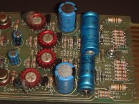
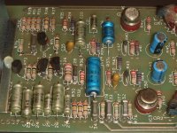
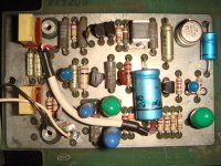
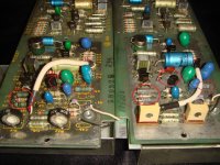
I've also posted photos of the circuit board. The left pic is the circuit under the shielded enclosure (as the schematic says), then the middle section and then the right side of the board.
Kevinkr - Ah great! Now I'm looking into replacements for the Harris HA2645's
A quick search brought up the Burr-Brown Opa445.I've also posted photos of the circuit board. The left pic is the circuit under the shielded enclosure (as the schematic says), then the middle section and then the right side of the board.
Attachments
> I'm just wondering given the extreme complexity of this design
> Lots of transistors and early, poor performing op-amps in the signal path
The complexity cleverly side-steps the possible opamp issues.
Q1 Q2 Q3 is a flat-gain low-noise amp which brings level far up out of the hiss of any chip. Assuming 1uV-2uV hiss from cartridge thermal resistance, gain-of-20 means the next stage should have hiss much less than 20uV.
Flat?? So where's the RIAA? The next stage *inverts* which allows an exact RIAA including infinite fall above 20KHz (non-invert goes flat-gain past the top of the audio band). The 1KHz gain is about unity.
HA2645 is a remarkable chip for its age. You sure can buy better specs today; I'm not convinced better specs mean better sound. Topology is complex but clean with hi-performance complementary process. Hiss is near 2uV, far below the 20uV needed to avoid stepping on thermal source hiss. Gain-bandwidth is "only" 4MHz, but this inverter runs unity-gain at 1KHz and there is over 80db NFB here. Slew is "only" 5V/uS but this allows "full" output well above the audio band. (Which does not matter to the RIAA stage but gets critical in the output stage.)
Also note the HA2645 is run direct on +48V (minus one diode-drop). Most standard chip opamps nominally explode at 36V, a few say 40V, and one says 44V. HA2645 is rated 70V. While I know a "36V" chip can live years on 37V, this point needs to be pondered before stuffing a "better" chip into a 47V hole.
So gain of 20 in front and unity-gain at 1KHz in the RIAA stage, gain of 20. We need more. The output stage is wired for gain of 22 to one output, inverted at the other, maximum gain is 880 at 1KHz, wow! You are going to want about 50K at "feedback gain" pins, to get it down in the 100-200 range we want for moving-iron needles. (The front-end is NOT optimized for moving-coil impedances.)
> Can +-0.2db be achieved?
It's certainly stable enough. I suspect R21 and R23, 1% parts, are the correct value. C16 may be a correct nominal value, and if it is 2% or better it should be fine.
The goofy part is C17 C18 and that "Boost" trim. Treble Boost is handy in broadcast, but you want "correct". Disconnect either R22 pot or C18. Change C17 to the right value. What's right? Either 3X or 4X C16.... I'm just not sure which factor is correct. My inclination is to go 2,050pFd at C17.
Then get Hagman's inverse-RIAA board, stable sig-gen and voltmeter, and trim the RIAA network. He only claims 0.5db accuracy, but note his plot of error with 5% parts gives 0.5db so Hagerman's and McCurdy's 1% parts should come in much better. And perhaps matching L/R is more important than absolute error... use the same iRIAA channel for both preamps and you can match them, far easier than trying to match without the iRIAA network.
> if the boards were switched, the problem followed the one board.
Quite odd. I am reminded that plug-in connectors speed servicing but were also THE most common trouble: tarnish on the contacts. Ground grime might throw crosstalk.
Also I think the two phono inputs need to float. R26 breaks ground between phono input and main ground. Some fraction of R26 ground-drop is led to the output stage. When output is taken differentially some ground-garbage should be canceled. If R26 is defeated with hard ground on the needle this may work against you.
Wow. Now that the holiday dust has settled...
PRR - Thanks for the great response.
I definitely have to get both boards performing equally as the trouble card has more gain and noise than its companion. There are definitely some component symmetry issues as one of the boards is of a different vintage.
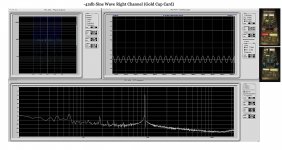
Firstly, Attached are 1k Sine wave tests that I did on both cards (while in the chassis). Just to confirm that the issue follows a particular card, Images 1 & 2 are the initial test. I then switched the cards (images 3 & 4) and did the test again. I'd appreciate your opinion. I did clean the contacts hoping that it would help but to no avail.
Also, I measured +57v at the power input for the cards (at the plug-in connectors without the cards installed). After installing one card the voltage dropped to +54v and after the second card was installed it dropped to +51v. The manual and schematic state +48v.
Matching Resistors - Under the shielding I noticed that there are two (apparently) different types of resistors at four locations. R6, R17, R5 & R8 (Left card with yellow writing is the orange cap card) differs from the right card. These resistors are low noise 1%. Should I bother replacing them with matching components?
I'm going to float the input ground and see if that helps any.
After resolving the larger issues I'll see about refining the RIAA curve and dealing with the Boost trim.
PRR - Thanks for the great response.
I definitely have to get both boards performing equally as the trouble card has more gain and noise than its companion. There are definitely some component symmetry issues as one of the boards is of a different vintage.
Firstly, Attached are 1k Sine wave tests that I did on both cards (while in the chassis). Just to confirm that the issue follows a particular card, Images 1 & 2 are the initial test. I then switched the cards (images 3 & 4) and did the test again. I'd appreciate your opinion. I did clean the contacts hoping that it would help but to no avail.
Also, I measured +57v at the power input for the cards (at the plug-in connectors without the cards installed). After installing one card the voltage dropped to +54v and after the second card was installed it dropped to +51v. The manual and schematic state +48v.
Matching Resistors - Under the shielding I noticed that there are two (apparently) different types of resistors at four locations. R6, R17, R5 & R8 (Left card with yellow writing is the orange cap card) differs from the right card. These resistors are low noise 1%. Should I bother replacing them with matching components?
I'm going to float the input ground and see if that helps any.
After resolving the larger issues I'll see about refining the RIAA curve and dealing with the Boost trim.
Attachments
-
 01) -42db sine wave Left Channel (blue caps) copy.jpg240.1 KB · Views: 117
 -
 02) -42db Sine wave Right Channel (Grey Caps) copy.jpg246.9 KB · Views: 101
 -
 03) -42db sine wave Left Channel (Grey Caps) copy.jpg250.1 KB · Views: 109
 -
 04) -42db sine wave Right Channel (Blue Caps) copy.jpg248.7 KB · Views: 101
 -
 both phono stages (non matching Resistors).jpg779 KB · Views: 125
I have always had good results replacing caps with Elna Silmic II's and Nichicon Muse series generally speaking. Nichicon FW for high uF that others (Silmic and KZ) dont cover, Nichicon KZ for values that Silmic II's dont cover...I tend to stick to this pattern of cap-rolling. Seems to work well for me so far.
...some have said that the Silmic II's give a tube-like sound. I think there is that elemental quality there..., to some degree....Comments have also been made regarding Elna Cerefine's have a sound similar to Blackgates, giving a more transparant and defined soundstage etc...I have not tried them as yet...
...generally, the 'tighter' the tolerance, the better....in caps and resistors. If the resistors are good quality, and are within spec/tolerance, and they are 1% and better than carbon, why replace them? If they are carbon, I would go for better than carbon resistors, and replace them all...
...personally, I would use a silver based solder, like WBT for silver with lead (low temp good flow euctectic for IC's and small trans etc) and/or Mundorf Supreme Silver lead free (for caps and resistors). I would desolder and then resolder with the above. I did this with a cheap TC-750 phono-pre-amp and replaced all the caps with Elna Silmic II's, with a higher voltage rating, and hard-wired output interconnects to it so that it plugs directly into the amp. It does not sound like it did; its a totally different animal now
Last edited:
- Status
- This old topic is closed. If you want to reopen this topic, contact a moderator using the "Report Post" button.
- Home
- Source & Line
- Analogue Source
- McCurdy Phono Pre and Replacement Capacitor questions