Does anyone have a simple circuit for generating say a 10 or 15Khz sine wave for feeding into a 3-head tape deck for optimal bias settings? Lots of decks have 3 heads and variable bias but not many have 15Khz tone generators. I know I can use my PC but would also find a standalone plug-in box useful as well. An output level of 100mV would be about right (at a guess)
Hello df_genius
Back in the seventies I worked as a tape transport designer for Scully Recording Instruments Co. in Bridgeport, Connecticut.
From those days I still have instruction manuals for the models 260, 280, 284 and 100. There are schematics of the various bias oscillators shown, but their frequencies are well above what you wanted. Some of the manuals are too thick to read on short notice but the models 260 and 280 use frequencies of 110KHz, 115KHz and 180Khz. I have to read the manuals for the models 284 and 100 to determine their bias frequencies.
If the above information is of use to you, I could scan the cicuits on my next trip to town. I live 20 miles from the nearest scanner.
Sincerely,
Ralf
Helo df_genius
After rereading your post, I realized that I may not have been of much help.
It occurred to me that, since every tape recorder has the bias oscillator built in, that was not what you were looking for. If that is the case, I am not able to help. Sorry for having wasted your time.
Sincerely,
Ralf
After rereading your post, I realized that I may not have been of much help.
It occurred to me that, since every tape recorder has the bias oscillator built in, that was not what you were looking for. If that is the case, I am not able to help. Sorry for having wasted your time.
Sincerely,
Ralf
Lots of decks have 3 heads and variable bias
but not many have 15Khz tone generators.
Hi,
Check the manual, quite a few later one
have automatic bias setting procedures.
My 2-head Yamaha does ....
rgds, sreten.
Simplest would be using Test tones from an MP3 player.
Last edited:
You could look at INFINEON|SAE800G|IC, TONE GENERATOR, SMD, SOIC8 | Farnell United Kingdom for instance but I would want to check the overall response of the tape machine after adjusting the bias so I would always use an audio generator of some sort. 15Khz is a bit high for bias adjustment unless you are running at 15 IPS.
Last edited:
A test CD with a range of frequencies (perhaps make your own if you can) is ideal. A frequency sweep is useful too.
As Barry mentions above, 15 k is far too high and also don't be tempted to under bias such that LF saturation is compromised. You might think you have got a good result at hf but find on audition that the overall result is awful.
I have fond memories of my old Aiwa ADF770 with auto bias, Eq and sensitivity that adjusted for every tape and Dolby HX Pro really pushed the hf response.
Check out this link for a build it yourself:www.diyaudio.com/forums/analog-line-level/200565-schematics-needed-3v-1khz-sine-wave-generator.html
The Eliot project has way too many parts for my taste, a split supply which is another 6-9 parts, plus some weird light bulb I don't have as a PTC Resistor. The EDN link for an amplitude stable oscillator leads to some op amp circuit using an op amp I don't have. I'm trying to build a 2 transistor oscillator from the GE Transistor manual 7th edition, it worked with a lot of hum imposed but when I put enough capacitance on the rail to get rid of the hum it just sits there. Have tried both 2n2905 at reversed polarity, and 2n3904 with as drawn polarity so far, got 6 mv out a little while but the o-scope sweep quit, I guess it blew the power supply. Don't know if the 6 mv was ~800 hz (with .025 uf caps) or hum. The GE circuit is not producing any tone I can hear through the amp I'm trying to repair, that does play a transistor radio a bit into a speaker before motorboating. BTW, the power supplie I have dedicated to this is a 4 amp 12 V CT battery charger transformer on an open frame that produces 19.5 V full wave rectified (1500 uf cap) or 9.5 V half wave rectified (2200 uf cap) both using the minus rail as reference.
The Exar XR2206 sine wave generator IC looks to be a lot more professional, but the nifty kit that was built on top of this is long gone. You can still get the IC in DIP package for $6 at newark.com. I have been trying to get it packaged with test circuit 12 on the datasheet (datasheetcatalog.com) but I've mostly proved solder sticks better to drill it yourself lexan and beigh CB boards than it does to socket pins. I've got some new $.85 DIP project boards from mcmelectronics, the DIP socket fits and solders fine but there is no room on it for the 15 discrete parts involved. I'm trying to fly the drill it yourself lexan board over the mcmelecttonics pcb, but holiday preparation has got in the way. Stay tuned, if anything works I'll draw it up on that original thread.
Last edited:
An upper limit for bias tone generator would be 10 Khz for any 1/4" tape machine or smaller (eg cassette 1/8"). You can substitute 20 Khz if the machine uses at least 1/2" tape and you are recording at 30 ips. 400 Hz is a good second tone, you only use the two. A 1 Khz tone can also be useful, however. Record the two bias setting tones at -20Vu (cassette) -10Vu (consumer tape deck) or 0Vu (professional tape deck). Ideally the playback will show the same Vu level as the record, but somewhat more important is the playback levels of the two tones relative to each other.
Grab some tape before you attempt a bias setting; ie don't use the tape at the start of the hub or reel ... wait until there's a minute or three of tape on the take up spool or hub, then start.
Once you find a tape formulation you like, use it exclusively. Every tape formula has a distinctive smell and some brands carry a distinctive family smell; it's relatively easy to learn how to identify a tape formula by smell alone by storing a reel of tape in a plastic bag as well as the box and just just sniffing the bag storing the tape.
Last edited:
Hello Johnny2BAD
An upper limit for bias tone generator would be 10 Khz for any 1/4" tape machine or smaller (eg cassette 1/8"). QUOTE]
With all due respect, Compact Cassette tape is 5/32" wide.
Sincerely,
Ralf
The width of the tape has no bearing on the frequency of bias test tones, the speed does.An upper limit for bias tone generator would be 10 Khz for any 1/4" tape machine or smaller (eg cassette 1/8"). You can substitute 20 Khz if the machine uses at least 1/2" tape and you are recording at 30 ips. 400 Hz is a good second tone, you only use the two. A 1 Khz tone can also be useful, however. Record the two bias setting tones at -20Vu (cassette) -10Vu (consumer tape deck) or 0Vu (professional tape deck). Ideally the playback will show the same Vu level as the record, but somewhat more important is the playback levels of the two tones relative to each other.
.
If you do a bias line up at 0VU, which is almost peak level, you run the risk of tape saturation giving a false result, especially at lower speeds and higher frequencies. The same applies for checking overall frequency response.
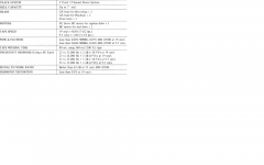
Thanks all guys. I said 15k as the Nak 682ZX and 680ZX I have do have 400Hz and 15Khz tone generators for setting bias. Yes I know most decks use lower frequencies for bias (the Sony TC-K75 I have and the Aiwa AD-6900's I used to have used 8Khz) but 15Khz is most suitable - I have a 482 and a 482X and two Akai GX-77's and 15Khz will be fine for those (the Akai is specc'd out to 26Khz at 0db and 33Khz to -20db).
Yes I know I could use an MP3 player, but this is DIY audio, so It'd be nice to create a simple circuit for it as well")
Yes I know I could use an MP3 player, but this is DIY audio, so It'd be nice to create a simple circuit for it as well
Attachments
Last edited:
Now I remember that unmistakeable Scotch smell (R2R) and early Maxell (Cassette) in the '70s with nostalgy...Every tape formula has a distinctive smell and some brands carry a distinctive family smell; it's relatively easy to learn how to identify a tape formula by smell alone by storing a reel of tape in a plastic bag as well as the box and just just sniffing the bag storing the tape.
- Status
- This old topic is closed. If you want to reopen this topic, contact a moderator using the "Report Post" button.
- Home
- Source & Line
- Analogue Source
- Tone generator for Bias setting on tape decks