I open this thread to discuss my Nobrainer circuit only. In my MPP thread i have tried out all kind of approaches and the question that comes more often then others " What is the best circuit ? ". I have tried to answer that question many times so i will only repeat that it depends a lot on the implementation. The same ( good ) topology can sound very different depending on active and passive part selection, building method ( 3D, Perfboard, PCB ), grounding and of cause PSU. Some say that they can even hear contacts, solder, mechanical coupling or decoupling, power cords, interconnects and other exotic accessory like Bybees and the like. So the MPP thread is very complete and detailed but also kind of confusing because of the many roads i have taken. This thread has has another philosophy. I will try to focus on only one circuit the Nobrainer.
As far as i can tell it is the most popular phono stage i designed. On the FF2011 alone where 3 versions of it, Georg´s on a PCB designed by Holger Barske,
another guy had made a 3D version and Holger had my original "Igel" ( porcupine ) in his system. i think the reasons are mostly simplicity and low cost but the circuit sounds very well too. It also performs well technically.
It is dead silent although i use 0.04 € input transistors, it is a transimpedance circuit with a high PRAT factor ( Power, Rhythm, Attack, Timing ) that a transcondactance stage hardly can match ( it´s possible but hard to do ) and it solves the major problem in a common base stage, the DC offset into the cartridge. Some people say that a transconducting ( or summing ) stage over
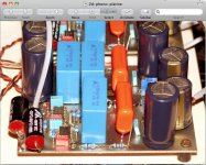
damps the cartridge including JC. That can happen when the cartridge impedance is rather high like in a high output MC. Shortening the inductance can then damp the treble. I have not made that experience, besides the input impedance of the Nobrainer can be adjusted over a certain range. Normally i set it at around 3.5mA and with that value it gave good results with my Lyra carts ( ca. 6 Ohm ), with the EMT´s and Denon 103´s ( 20 to 40 ) 9 and even in system with a 20 year old High Output Audio Technica MC. We played that cartridge on FF2011 on a system from our russian friends and the Nobrainer did not sound much worse then a very expensive siberian tube phonostage with an Auditorium 23 transformer. I was surprised. I will check where i find the specs of the Audio Technica. Andre`said that he found it after 20 years in the waist bin. It played just fine, i would even say spectacular on a restored Lenco L75 so please do not tell my great vinyl must be ultra. The russians, not stupid, had placed the table on an enormous substructure though. I will post a photo. Ok, so some think it´s over damped with a TI ( transimpedance ) stage, other have said like Tominari and Candeas taht it acts like a damper in the suspension of a car, preventing rattle by shorting the moving coil and acting like an eddy current brake. Anyway, i and people i trust like the Nobrainer as is. The last 3 days i have also being working on a discrete version. So there is some new wine in old bottles. So here is the original
circuit. More to come.......
As far as i can tell it is the most popular phono stage i designed. On the FF2011 alone where 3 versions of it, Georg´s on a PCB designed by Holger Barske,
another guy had made a 3D version and Holger had my original "Igel" ( porcupine ) in his system. i think the reasons are mostly simplicity and low cost but the circuit sounds very well too. It also performs well technically.
It is dead silent although i use 0.04 € input transistors, it is a transimpedance circuit with a high PRAT factor ( Power, Rhythm, Attack, Timing ) that a transcondactance stage hardly can match ( it´s possible but hard to do ) and it solves the major problem in a common base stage, the DC offset into the cartridge. Some people say that a transconducting ( or summing ) stage over
damps the cartridge including JC. That can happen when the cartridge impedance is rather high like in a high output MC. Shortening the inductance can then damp the treble. I have not made that experience, besides the input impedance of the Nobrainer can be adjusted over a certain range. Normally i set it at around 3.5mA and with that value it gave good results with my Lyra carts ( ca. 6 Ohm ), with the EMT´s and Denon 103´s ( 20 to 40 ) 9 and even in system with a 20 year old High Output Audio Technica MC. We played that cartridge on FF2011 on a system from our russian friends and the Nobrainer did not sound much worse then a very expensive siberian tube phonostage with an Auditorium 23 transformer. I was surprised. I will check where i find the specs of the Audio Technica. Andre`said that he found it after 20 years in the waist bin. It played just fine, i would even say spectacular on a restored Lenco L75 so please do not tell my great vinyl must be ultra. The russians, not stupid, had placed the table on an enormous substructure though. I will post a photo. Ok, so some think it´s over damped with a TI ( transimpedance ) stage, other have said like Tominari and Candeas taht it acts like a damper in the suspension of a car, preventing rattle by shorting the moving coil and acting like an eddy current brake. Anyway, i and people i trust like the Nobrainer as is. The last 3 days i have also being working on a discrete version. So there is some new wine in old bottles. So here is the original
circuit. More to come.......
Attachments
I am now out of the concept phase for the Nobrainer Discrete. There will be two versions,
one runs on 12V batteries and the other runs on plus-minus 24V from a PSU that i designed.
I ended up with a circuit that is conceptually as simple as possible. When you look at it you will see that the signal goes only through two BJT transistors and one Fet. In fact in the final circuit there will be two resistors also in the signal chain but the circuit also works without them. At first i tried to improve on the original Nobrainer input stage and one of the inspirations is the ATS MC preamp by Rabeylolles. When it came out in the Autumn 1986 issue of L`Audiophile it was revolutionary and visionary. No other phono input stage fascinated me as much over the years and i also needed years to really understand it. The principles he uses i would call multi use and entanglement. In principle it is the parallel symmetric version of the simple Hiraga current mirror. The differences are besides the symmetry that he supplies the mirror with current sources and adds folded cascodes to make DC coupling possible. Bias to the folded cascodes is from a symmetric current source that is referenced to ground so allows DC offset trim. The current sources that supply the mirror make also sure that the folded cascode sees a high impedance so open loop gain is high. He then feds back the output signal to the current mirror. As a real twist he feds the bases of the folded cascodes with a level shifted version of the Ube generators in the mirror. You can find the circuit and others on the Claudio Bonavolta - Photography - Web Design website. So i did my take on the ATS. See my NOCMUS circuit. That stands for No Capacitor Multiple Use. I use only two current sources instead of the ATS´s 4. I simply level shift the current with a diode and feed it into the bases of the folded cascode. A buffered copy of the input signal feeds this point too. The input transistors are cross cascoded with a driven cascode and the second transistors of the input diamond feed the emitters of the folded cascode. Guess what ? It worked although only over a narrow dynamic range until deformation of the input signal set in. I could put more work into this put i put it aside for the moment. The ATS has one disadvantage that bothers me. By using the Ube generators there is always a 3dB noise penalty. Especially the way he designed it with feedback. His stage has the noise of a 130 Ohm resistor and that is rather poor after modern standards. I am thinking more about a noise impedance that is 5 to 10 times lower.
Attachments
Here is a more detailed circuit of the Nobrainer Discrete. I have not build it yet so details may change like the servo and the values of the RIAA components. I also have an idea for a line input with volume control so the buffer can be used for CD too. I will also present a list of transistors that can be substituted, Fets and bipolars because this circuit works with a wide variety of active parts and you may not have the ones in the schematic. The 2N4401, 2N4403 combination are the classic low noise transistors from the 60th, used for example by JC in the original Mark Levinson JC1 MC pre-pre. They still work in this position. They have an Rbb´of 40 Ohm and medium Hfe.
Attachments
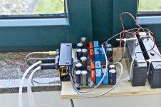
I promised Holger Barske to publish a PSU design for the Nobrainer. The design is based on a circuit that Holger made for the Dispre. I spotted a mistake and made some additions that improve performance : I added common mode chokes, i changes the resistor that supplies the TL431 to 220 Ohm. Holgers original value of 10kOhm will not work. The TL431 needs at least 1 - 2mA to work correctly and the 10kOhm will give only 0,65V / 10000 = 65uA. Maybe this was a typo. I added 220 uF to the adjust Pin for less noise. This is a very simple PSU that nevertheless works and sounds very well.
Circuit comes with the next post.
Circuit comes with the next post.
I forgot the smoothing caps. Sorry, here the devil is in the details and not god i am afraid.
Also a fuse should be used on the 230V AC side. My program can not draw a fuse, sorry.
I build this and it works. The common mode choke could also be put directly before the regulator after the 2200uF-10Ohm-2200uF filter bank. I have not tried this though. I would not put it after the regulator because the nice low 20mOhm output impedance would get lost. The choke has around 1.5Ohm.
Attachments
Here are my latest thoughts on the Nobrainer Discrete. This time the input stage is a diamond buffer. It can be also configured " the other way around " as a transimpedance input stage. The RIAA is active, driven by a class A output stage. The second stage is a Hawksford cascode also known as driven cascode. It returns the base current of the cascode into the amplification chain. Hawksford was not the one that invented it, i think Borbely was first ( but he never used it ), but it was baptized after Malcolm.
I like the circuit a lot. When the bias servo works it needs no adjustments. The RIAA caps are from small values, the circuit is economical with only 14 relatively cheep BJT´s, no expensive low noise Fets are needed, it´s DC coupled. PSU rejection should be good.
The only disadvantage i see over the earlier Nobrainer is that now the input transistors are in series and there are 5 Ohm emitter resistors plus the 10 Ohm feedback resistor to ground so this is somewhat more noisy. The normal Nobrainer has around 20 Ohm noise impedance with the recommended transistors and this one would have 55 Ohm, on par with an AD797 that is considered " ultra low noise". Part of it can be canceled by using lower Rbe`transistors. With 2 Ohm transistors noise would be approximately 20 Ohms again. 6dB better then the AD796. I think this is no world record but decent.
Attachments
Hi joachim: AFAIK, the "Hawksford" cascode was invented by Roy M. Hayes of Tektronix. The patent was filed in 1964, and was granted in 1969. The US patent number is 3423685, and the patent calls the circuit "bootstrapped cascode differential amplifier".
The circuit was being used by various US amplifier manufacturers such as Spectral in the mid-1980s, possibly earlier. Whenever I talked with Demian Martin or the other guys in or around Spectral, the circuit was called "bootstrapped cascode."
The circuit was also used by Japanese designers by the 1980s - some of the Japanese circuit-oriented books and magazines that I have from that period show this topology in use, although I would have to dig through the articles to recall what the circuit was called.
In fact, I first may have heard the term "Hawksford cascode" from you (grin).
hth, jonathan
Thanks for that information. Malkolm introduced it to me in the early 90th but he never has claimed to have invented it. He made an AES paper that goes into much detail though.
That made that circuit somewhat popular with some.
I was not the first that used the name Hawksford Cascode. I think i got this name from this very forum but i am guilty to spread the name even more although it is not 100% correct. A japanese would never do that") sorry, it´s not even artistic freedom, just lazyness.
sorry, it´s not even artistic freedom, just lazyness.
That made that circuit somewhat popular with some.
I was not the first that used the name Hawksford Cascode. I think i got this name from this very forum but i am guilty to spread the name even more although it is not 100% correct. A japanese would never do that
sorry, it´s not even artistic freedom, just lazyness.He calls it "Enhanced Cascode".
http://www.essex.ac.uk/csee/research/audio_lab/malcolmspubdocs/J10 Enhanced cascode.pdf
http://www.essex.ac.uk/csee/research/audio_lab/malcolmspubdocs/J10 Enhanced cascode.pdf
Thanks when you try. That will safe me some time. I usually use the version after the diodes and it sounds really good but i maybe wrong.
Mr. John Curl uses CM chokes on DC side of PS in all current preamps he has designed, including Parasound JC-3 phono preamp.He got rave reviews for them, so he is on the right tracks.
I tried CM ckokes in the same way and got better dynamics and low level details. UI cores dual section CM chokes which I use are better than ring core types, and cheaper too.
- Status
- This old topic is closed. If you want to reopen this topic, contact a moderator using the "Report Post" button.
- Home
- Source & Line
- Analogue Source
- JG´s Nobrainer and Nobrainer Discrete