Here is the pin out of the BC327/337 :
http://www.fairchildsemi.com/ds/BC/BC337.pdf
http://www.fairchildsemi.com/ds/BC/BC337.pdf
Et voila
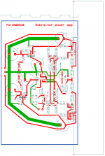
Here you have my latest layout.... Please disregard the previous ones that might have errors in the output stage connections.
I would just appreciate your comments on the placement of the parts and particularly on the GND layout and smoothing caps.
I will off course study the pinouts carefully before implementation.
Does this design ever work in class AB ?
Attachments
I just came back from the Vienna Show. A 12 hour car ride by night.
At first glance i would do the PSU and ground traces quite a bit thicker.
Well, where does Class B stop and Class AB start ?
The only " hard " Class B HiFi Amp i know is the current dumper in the Quad 405 ( and siblings ). There is absolute no bias i think. Even the small bias i use in the Szikley output stage of the Nobrainer amp i consider as Class AB. Curiously when you read Self a Szikley has minimum distortion at very low bias. He shows that graphically as the waveform in transit from the NPP to PNP output transistor. When you " over bias " a Szikley, the distortion goes up. Unfortunately he does not show an FFT spectrum so it well can be that mostly second rises when you go from say 15mA to 125mA of my prototype. That can sound " warmer " or " better " although THD as such goes up.
This one can be used if more power is required :
http://www.ti.com/lit/ds/sbos100a/sbos100a.pdf
http://www.ti.com/lit/ds/sbos100a/sbos100a.pdf
")
Using a +-35V psu, how much power can this circuit deliver into a 4ohm load ?
I * I * R
V * V / R
300 watts..... must be conservative with the heatsink.... But this would only be possible if the psu could deliver 8 amps to the speakers and also if the amp output buffer would be able to swing the full rail voltage.
It seems strange because my actual amp runs with +-35v rails and it is rated 30watts max output at 8 ohms... with 4 ohms it will never output more than 50watts.... there is some kind of current limiting.
It seems strange because my actual amp runs with +-35v rails and it is rated 30watts max output at 8 ohms... with 4 ohms it will never output more than 50watts.... there is some kind of current limiting.
Using a +-35V psu, how much power can this circuit deliver into a 4ohm load ?
Easy, for 35V equals 32V out equals 32/4 equals 8A taking in account possible blind currents and LS out of phase with supply and 'counter EMF' (lets say 50%) then you may expect up to 12A needed.
The power output RMS will be 32V/Sqrt(2) equals 22V equals V*V/R equals 128Watt (do not try this at home (with one pair of the proposed transistors)) (average being lower, then you need to use Sqrt(3) as a divisor).
When bridged, you double the voltage and quadruple the output (theoretically), it goes up to 500Watt. But you now must be able to deliver almost 25Watt (no headroom).
Maybe 100Watt driving a bulb, or 25Watt average driving a LS with some headroom (not to much).
You better start building something with a front plate like this http://www.flickr.com/photos/fransdewit/10906631896/ (that is 200mm x 540mm x 10mm).
Counter-electromotive force - Wikipedia, the free encyclopedia
http://en.wikipedia.org/wiki/Audio_power
http://yeroc.us/eng/pmpo
Last edited:
Here is a simple case of a Class B amp and how feedback works :
The magic of negative feedback | EDN
The magic of negative feedback | EDN
Here is a classic paper about crossover distortion in a Class B amplifier :
http://hifisonix.com/wordpress/wp-c...oss-Over-Distortion-in-Class-B-Amplifiers.pdf
It is for the simple case of a parallel symmetric emitter follower.
The output stage of the Nobrainer is different. It is a CFB pair or Szikley.
This variety is best covered in Douglas Self´s book " Audio Power Amplifier Design ".
I recommend to buy the new 6th edition.
- Status
- This old topic is closed. If you want to reopen this topic, contact a moderator using the "Report Post" button.
- Home
- Source & Line
- Analogue Source
- JG´s Nobrainer and Nobrainer Discrete