Yes Frans, that is true for an EF follower ( Self give somewhat over 100mA, depending on the emitter resistors, that has to do with that famous 24,5mV ) but this is a CFP ( Szikley ) with 100% feedback so optimum bias is much lower if you do not bias high into Class A.
Yes that is true (it's different for the CFP as compared for the EF), but still I think 50mA (or even lower) is a bit too low for my expectation. This (it being an expectation) is good ground for experimenting. Currently (in my amp project) I am using BIGBT's (Laze Cat style) output compound devices and I am biasing them as EF's (that is 100mA for each output device).
I am really looking forward how your amp ...
Yes, me too
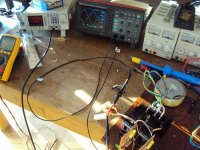
") Last saterday the board was compleated, sunday during the day it was mounted, and sunday evening I destroyed it
Last saterday the board was compleated, sunday during the day it was mounted, and sunday evening I destroyed it After first power up I could not set idle current, so I took the meter and the nearest probing pin (it was a (to) large one), and started metering some points. The next thing is, I shorted 70 Volts against the Vas-cascode, this destroyed the cascode and put lots of volts on the opamps... you can guess it from there.
Next weekend there will be time, and the fight goes on ... will be continued ...
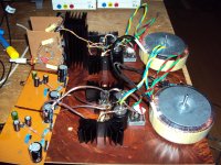
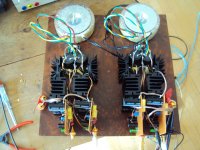
Puh, one channel of the SBP bridge is ready. That was more work then i thought. I use bigger heat sinks now and put the amp modules vertically for chimney effect. After a lot of head scratching i decided on 125mA idle. I the spirit of DIY i decided on the simplest option : Non inverting amps and Elliot bridging. The bridge puts out plus-minus 17V P-P into 6.6 Ohm. That is around 30W RMS depending on load. I think that is useful. The other two amps are prepared too so maybe i get it complete until the weekend.
Attachments
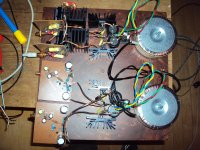
I am still working on the other channel of the bridge. It should be ready saturday night.
I supply the modules with a PSU but it can be driven by a plus-minus 12V battery.
The PSU is a mix of a MosFet cap multiplier and a Zener stabilization.
I supply the modules with a PSU but it can be driven by a plus-minus 12V battery.
The PSU is a mix of a MosFet cap multiplier and a Zener stabilization.
Attachments
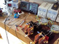
The two other channels are ready ! Besides an exploding 4700uF 35V Low ESR Elcap i inserted the wrong way as it is traditional at Maison Gerhard it went smooth.
This explosion was kind of interesting. Modern Elcaps have slots in the top. This cracked open and and some gas came out with a load "ZZZZZZSSSSHHH". It did not smell so this was kind of a surprise. At closer look there is some yellow fiber that came out. That may have sucked up the electrolyte. Good safety measure. 30 years ago this whould have being a real disaster with teribly smelling electrolyte all over the place, and they are very small now. A 4700uF 35V was as big as a glass back then.
This explosion was kind of interesting. Modern Elcaps have slots in the top. This cracked open and and some gas came out with a load "ZZZZZZSSSSHHH". It did not smell so this was kind of a surprise. At closer look there is some yellow fiber that came out. That may have sucked up the electrolyte. Good safety measure. 30 years ago this whould have being a real disaster with teribly smelling electrolyte all over the place, and they are very small now. A 4700uF 35V was as big as a glass back then.
I have now listened more. Dynamic range is expanded much. The bridge sounds also somewhat more open so i needed some time to find the right cabling and adjustment of the subwoofer. It has 6db more gain to begin with so initial impressions may have being spoiled somewhat by too low gain in the subwoofer chain. The slightly sweat character of the unbridged version is gone. It sounds basically very neutral with good resolution. That can be because i reduced the bias somewhat or it is an effect the bridge has on the distortion spectrum. Theoretical the bridge should suppress second harmonic.
For now i am satisfied. More to come.
For now i am satisfied. More to come.
I have worked with Ward Maas on finishing the circuitry of the SBP. The bias scheme is now automatic. Ward also choose the NE5534 because it can be run on plus-minus 20V for more power without bridging. An LME49870 can be used for even more power because it can stand plus-minus 22V.
Holger had a nice idea how a bridging adapter can be avoided : Use a balanced line stage.
I found a circuit that can be used or modified.
Holger had a nice idea how a bridging adapter can be avoided : Use a balanced line stage.
I found a circuit that can be used or modified.
Attachments
I have looking to the circuit and wonder why the current mirror ?
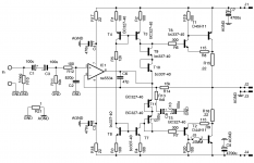
T3 T4 T7 T8 T9 T10 T11 T12 are Vas right ?
T3 T4 T7 T8 serve the purpose of current source ?
T10 and T11... are these diodes intended for biasing the output stage ? (like a bias spreader) ?
What are R13 R14 C9 and C10 for ?
What is the purpose of J5MM ?
Please bear my basic questions as I am trying to learn how the circuit works before I start to pick up parts.
T3, T4, T7, T8 form a bipolar current source. The configuration as a symmetrical Widlar mirror makes sure that the same current appears on both output nodes.
This amp has no VAS as such. The opamp provides most of the voltage gain.
The current mirror gives a high impedance for the opamp helping linearity by not much loading the opamp. This also maximizes open loop gain and gives some PSU rejection.
There is some voltage gain in the OPS but it is localized. This is a Szikley ( CFP 100% current feedback ) where the current comes
out of the collectors of the ouput transistors. This is a bit like Theshold Stasis but with the Szikley wrapped in an overall voltage feedback loop.
T9, 10, 11, 12 form a string of Ube transdiodes making the output stage conduct. The Szikley OPS does not need much idle current so this is close to class B. You can increase the idle by adding Ube diodes in the string. You can measure the idle in R15, 16.
R13, R14 provide overall voltage feedback, C9,10 block DC so DC gain of this amp is only x 1. That makes a servo obsolete.
You can use a foil cap instead of C1,3.
I can not remember what the jumper is for. It breaks the base current on the negative side so this output transistor does not conduct any more. It may have to do with testing.
Thank you
What is the difference between GND and AGND ?
What is the purpose of R11 and R12 ?
I like the Elcap bipolar arrangement and still have some good bipolar BG around, so I will try those in the first attempt.
I have also some 4562 opamps that I believe can replace the ne5534.
Is it possible to use a fet input opamp in order to avoid input caps ? If so what would you recommend ?
One is audio ground, the other cabinet ground when it is from metal.
R11 sets the input impedance. You can make that higher ( up to say 47kOhm ) if you wish but 10kOhm is less prone to noise injection.
R12 forms a low pass with C2 to roll go HF.
Yes, you can use 4562. We close NE5534 because it can stand up to plus-minus 22V so the amp has enough power. There is an opamp from National in the same series then 4562 that also can stand more voltage.
You can use a Fet opamp like the OPA1641 but watch the maximum PSU voltage allowed.
- Status
- This old topic is closed. If you want to reopen this topic, contact a moderator using the "Report Post" button.
- Home
- Source & Line
- Analogue Source
- JG´s Nobrainer and Nobrainer Discrete