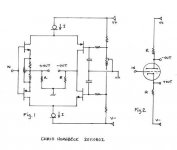
The 50 Ohm resistors i crossed have to be 10 Ohm. So 25mV is developing over the 10 Ohms. That also sets the idle in the output stage.
The emitter loads of the input BJTs are bootstrapped with a copy of the output signal.
That way they see a high impedance. This is simpler then the current mirror you see here usually and works very well too. The collectors are connected to the output transistors and not to the opposite supply as usual.
Yes, you can use other N-Channel J-Fets as long as Idss is higher then the current you want to send into the circuit. Which one can you get ?
J310 for example ? The higher the Idss is to begin with the more you can degenerate the Fet and that usually increases output impedance, thus improving PSRR.
J310 for example ? The higher the Idss is to begin with the more you can degenerate the Fet and that usually increases output impedance, thus improving PSRR.
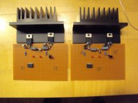
The work on the SBP ( Solar Batterie Poweramp ) made some progress.
I simplified the output stage to a CFA ( Szikley ) and added the possibility of current drive.
3 kinds of drive are now possible :
Voltage Drive
Current Drive
Open Loop ( output stage not in the feedback loop like Stasis )
Circuit diagram will follow when the prototype works as advertised.
I simplified the output stage to a CFA ( Szikley ) and added the possibility of current drive.
3 kinds of drive are now possible :
Voltage Drive
Current Drive
Open Loop ( output stage not in the feedback loop like Stasis )
Circuit diagram will follow when the prototype works as advertised.
Attachments
Last edited:
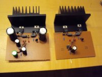
The SBP is under current.
So far no unexpected problems.
I set the bias quite high on my samples : ca.500mA.
Bias ramps up slightly by 20% over the first minutes so temperature coefficient is slightly positive. It stabilizes well after that but i will let it run for a while if there is any tendency to run away too high.
Cooling fins get rather warm so i may reduce the idle later.
Attachments
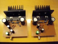
The SBP is working ! I reduced the idle to 200 - 250mA because the cooling fins got a little too hot. I measured 4,9W into 6.6 Ohm, 7.5W into 4.4 Ohm and 9.8W into 2.2 Ohm. This is the RMS value.
Into 2.2 Ohm some compression is visible but no crossover distortion, at least visually on the scope. Peak to Peak voltage is plus - minus 8V on 4.4 Ohm and 6.6 Ohm and 6.5V into 2.2 Ohm. That is around 3A of current into 2.2 Ohm. That should be sufficient for medium volume on 90dB efficient speakers and with more then 95dB efficiency it can play rather loud. This is no Rock and Roll amp anyway. This could also be a rather awesome headphone amp. Stabilty on capacitive load is good without a Zobel or a coil.
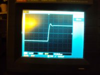
A 100nF parallel to the 4.4 Ohm dummy load gave just a bit sharpening on a 10Khz full output square wave and a 4.4 Ohm - 1uF combination gave a clean overshot. A dynamic speaker with a low inductance cable should give no problem. An electrostatic would need a coil and a Zobel but this is not the ideal amp for electrostatics anyway, they usually need more power because the have low efficiency and can go under 1 Ohm in the treble. I did not try to squeeze an ultra wide response but i get a decent bandwidth from 4 Hz to 100 KHz -3dB. I use simple Miller compensation but i plan to experiment with output inclusive compensation ( Self - Baxandall ) for even less distortion in the treble. Now i will put some speakers on.
Into 2.2 Ohm some compression is visible but no crossover distortion, at least visually on the scope. Peak to Peak voltage is plus - minus 8V on 4.4 Ohm and 6.6 Ohm and 6.5V into 2.2 Ohm. That is around 3A of current into 2.2 Ohm. That should be sufficient for medium volume on 90dB efficient speakers and with more then 95dB efficiency it can play rather loud. This is no Rock and Roll amp anyway. This could also be a rather awesome headphone amp. Stabilty on capacitive load is good without a Zobel or a coil.
A 100nF parallel to the 4.4 Ohm dummy load gave just a bit sharpening on a 10Khz full output square wave and a 4.4 Ohm - 1uF combination gave a clean overshot. A dynamic speaker with a low inductance cable should give no problem. An electrostatic would need a coil and a Zobel but this is not the ideal amp for electrostatics anyway, they usually need more power because the have low efficiency and can go under 1 Ohm in the treble. I did not try to squeeze an ultra wide response but i get a decent bandwidth from 4 Hz to 100 KHz -3dB. I use simple Miller compensation but i plan to experiment with output inclusive compensation ( Self - Baxandall ) for even less distortion in the treble. Now i will put some speakers on.
Last edited:
The power limit here is more the rather low voltage on which the amp runs. This is limited because the amp is designed to play on solar power with batteries. The output transistors are rather robust and with say plus - minus 24V could be pushed to 25 - 30 W. Under this conditions i would increase the size of the cooling fins.
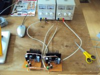
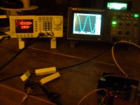
Here are some pictures of the session tonight.
16 V P-P into 6.6Ohm.
10kHz square.
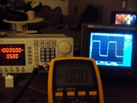
10Khz square into 4.4Ohm plus 1uF.
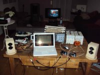
Listening setup.
I was able to listen a bit. I used my I-Book and the little Watsons i build for the Linkwitz experiment.
The amp is quiet. I can not say much about the sound but there is good separation and it even throws a quite deep soundstage in the near field.
I will post the schematic i have at the moment tomorrow. It is kind of late here.
16 V P-P into 6.6Ohm.
10kHz square.
10Khz square into 4.4Ohm plus 1uF.
Listening setup.
I was able to listen a bit. I used my I-Book and the little Watsons i build for the Linkwitz experiment.
The amp is quiet. I can not say much about the sound but there is good separation and it even throws a quite deep soundstage in the near field.
I will post the schematic i have at the moment tomorrow. It is kind of late here.
Attachments
Last edited:
Thanks, i will try plus-minus 17V before i start to listen. That is the maximum the LME49710 Opamp that i use can take. The LME49860 is the same but can stand plus-minus 22V.
So plus-minus 22V is the maximum on which i can run this amp. There are other Opamp based designs that take the signal out of the PSU pins with common base stages like the Kuroda but i decided on the simpler Power Opamp topology.
So plus-minus 22V is the maximum on which i can run this amp. There are other Opamp based designs that take the signal out of the PSU pins with common base stages like the Kuroda but i decided on the simpler Power Opamp topology.
- Status
- This old topic is closed. If you want to reopen this topic, contact a moderator using the "Report Post" button.
- Home
- Source & Line
- Analogue Source
- JG´s Nobrainer and Nobrainer Discrete