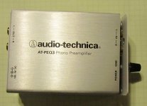
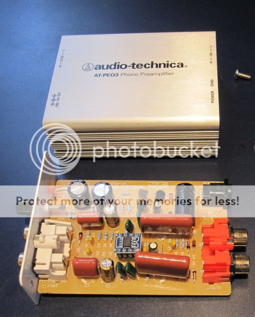
i see these have been discontinued, so if you find one, you can pick them up cheap. i just wanted to know what's inside, since i haven't seen any pictures anywhere else. so, here you go. enjoy ...
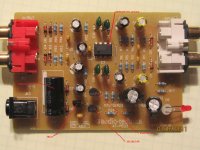
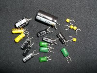
and, no, i haven't listened to it yet. first, a couple of things have to go immediately ... like those 220pF cartridge loading caps.

mlloyd1
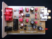
oops, sorry about the picture size for the first one. i wanted that one big since i knew that's the one you all wanted to see.
works best to click and save to hard drive before viewing ...
and, no, i haven't listened to it yet. first, a couple of things have to go immediately ... like those 220pF cartridge loading caps.
mlloyd1
oops, sorry about the picture size for the first one. i wanted that one big since i knew that's the one you all wanted to see.
works best to click and save to hard drive before viewing ...
Attachments
Last edited:
i asked for a schematic - yeah, yeah, i know, i'm being lazy.
i'll let you know if i actually get something in response.
i wonder why folks make the power rails so low in these little preamps?
using higher supply voltages seems a quick and easy way to get some headroom benefits and improved distortion specs for starters.
i'm surprised nobody here posted anything about modifying one - especially since I've noticed it got a little positive buzz in stereophile not long ago. seems a prime candidate for mods - provides a nice little case, uses through-hole parts and uses an opamp that many people would love to change out.
mlloyd1
using higher supply voltages
Well, there are not so many nice high voltage opamps out there
And distortion is usually not much of a problem for opamps anyway.
Still - a schematic would be fun!
Hannes
wow, ask and ye shal receive, as they say ...
enjoy,
mlloyd1
enjoy,
mlloyd1
i asked for a schematic - yeah, yeah, i know, i'm being lazy.
i'll let you know if i actually get something in response
....
mlloyd1
Attachments
I took a look at the schematic. Dissapointing to say the least.
Single ended, running off a low supply voltage (fully agree with your observation MLloyd1) to save just a few pennies. A split rail supply would have avoided all the shenannigans around the half rail reference circuitry, and they could have dropped the transistors (or better still, used them for an output stage buffer, enclosed in the overall feedback loop).
Another concern is the rather high resistor values used for the feedback netowork. If they had used lower value resistors (which would of course require larger RIAA equalization caps) this pre-amp could have been a lot quieter.
One good thing about this RIAA of course is that it is fully active, which means the best possible overload characteristics. That said, you could also argue that they can get away with a lower supply rail as a result . . .
However, I would have done it a bit differently . . .
Thought i would resurrect a post- I set up a turntable in the living room which is primarily TV/AV room. The distance required a 10 foot cable to the Pioneer Elite VSX-39TX. Using the onboard phono stage rolled the highs off a bit. I had PEQ3 on a shelf so decided to use it as a line level source. Replaced the cheap electrolytics, put in a socket and rolled some op amps. Currently have LME49990 SMD singles on an adapter. Beat the LM4562 with same detail but not as harsh. Soundstage is wider, better bass with great attack. For a bargain basement pre, $15 in parts made a big improvement.
Fasterdamnit:
thanks for sharing your results. i'm curious; it looks like you did not make any changes to optimize the preamp loading to your cartridge?
also, does your ground terminal work well? mine didn't because of the paint. i changed the screw after sanding the paint off around the hole.
mlloyd1
thanks for sharing your results. i'm curious; it looks like you did not make any changes to optimize the preamp loading to your cartridge?
also, does your ground terminal work well? mine didn't because of the paint. i changed the screw after sanding the paint off around the hole.
mlloyd1
Fasterdamnit:
thanks for sharing your results. i'm curious; it looks like you did not make any changes to optimize the preamp loading to your cartridge?
also, does your ground terminal work well? mine didn't because of the paint. i changed the screw after sanding the paint off around the hole.
mlloyd1
Hi, ML. I just clipped one leg of the 220pf input caps. Yes, I removed paint around the ground lug. I am looking into swapping in a 24Vdc supply. I think I have one buried in the junk box. I need to see what the regulator is rated.
Update: I found a spare 24vdc wall wart and decided to see if it would be an improvement. I replaced all 8, 15v zener diodes and the regulator with 24V ones. The caps I installed previously were at least 25vdc. Just started playing it but can't really turn it up til later tonight. Sounds quite good at moderate volume. Another ~$3 thrown at the entry level pre...
I had another short look wether that circuit takes also higher rails and indeed it seems as long as the caps and the opamps are suitable.
However, that was completely banana. Q1/Q2 act simply as 2 switches for whatever reason. These bjts run fully turned on during normal operation.
Hannes
the japanese bipolars are only used as 2nd regulating stage after the IC-regs.
However, that was completely banana. Q1/Q2 act simply as 2 switches for whatever reason. These bjts run fully turned on during normal operation.
Hannes
I had another short look wether that circuit takes also higher rails and indeed it seems as long as the caps and the opamps are suitable.
However, that was completely banana. Q1/Q2 act simply as 2 switches for whatever reason. These bjts run fully turned on during normal operation.
Hannes
I made sure before I started soldering. I wondered why the transistors were there, current regulation?
An alternate modification
I have recently finished upgrading my AT-PEQ3.
First of all I made a change to the power supply, which had to be replaced with a 230V one, so I built my own. Finally it was modified to be slow-turn-on in order to limit the thump when powering on the AT-PEQ, which could potentially kill a USB-powered sound card.
Second of all the original input capacitor was 1000µF 25V, the voltage rating of which is easily exceeded using the supplied 18V unregulated power supply, or any other suitable power supply. Therefore I replaced this one with a 35V type.
Furthermore I replaced the following capacitors:
Ceramic capacitors were replaced with PP film capacitors, except two 100nF bypassing caps.
The two 1.5nF Mylar capacitors were replaced with WIMA polypropylene
The two 5.6nF Mylar capacitors were replaced with Nichicon polyester (due to unavailbility of this value with WIMA and space restrictions)
The 1000uF 25V input capacitor was replaced with a 560uF 35V Panasonic FM (I would suggest to use acapacitor having no more than 20mm height, such as FM 470uF 35V, as this one was hard to fit.)
The 220uF 25V supply capacitors were replaced with 220uF 25V Panasonic NHG
The 10uF 25V bypass capacitors were replaced with 10uF 50V ELNA Cerafine.
The 47uF 25V feedback capacitors were replaced by 47uF 25V ELNA Cerafine.
The electrolytic coupling capacitors (0.47uF and 4.7uF) were replaced by WIMA MKS. By the way these capacitors are ideal for replacing electrolytics because they have the same lead spacing (2.5mm up to 1uF and 5mm up to 4.7uF). I prefer this in order to keep the leads short.
At this point I did not replace the NE5534, but if I wanted to then I would use the LME47920 (PIN compatible DIP version). I have used the LM47910 as a replacement for the NE5532 in another project.
I have observed two deviations from the schematic:
1. My unit is using a 78L18 regulator, not a 78L15 one.
2. The 100nF ceramic capacitor is across the input and output pins of the regulator, not across input and ground (although I do not understand the purpose.)
In case someone wants to perform th esame upgrade, all components can be sourced from Banzai Music. The AT-PEQ3 can still be sourced from LP Gear, although the price has increased since I purchased my unit.
I did not have the time to compare the sound before and after the modifications, but wanted to make some basic improvements. Soundwise I am very happy with the unit, and I must say that its mechanical construction is very solid.
Attachments
I made sure before I started soldering. I wondered why the transistors were there, current regulation?
They're there for pop/thump mitigation nothing more, they disconnect the supply from the op-amp when the voltage is less than approximately 7V..
Pay attention to the cartridge load which stock is only ~32K. Replacing the 47K input resistor with something like 90.9K will get you close to the recommended 47K (47.6K).
Dump the zeners on the inputs and outputs - they're there for nothing more than cheap ESD protection, and with just a little care should not be be necessary under most circumstances. A properly chosen TVS would be a better choice than the zeners on the supply, and a resettable fuse between power connector and TVS/pre-amp circuitry would provide protection against an external supply malfunction or backwards connection.
Higher supply voltages cannot hurt, but if running on 24V supply, you should change any 25V capacitor across the rails to 35V - any others should be OK as is.
Thank you so much for explainig the transistor circuit. I am positively surprised that this was given some thought, and it is probably effective when unplugging the power supply. However it should not change much (if at all) during power-on.
Yeah, the half supply bias network has a long enough time constant I suspect to handle the turn on thump if not completely eliminate it. Obviously some thought went into power sequencing I imagine with a view to not generating speaker damaging transients if possible.
Overall this is a much better design than the ones that were around when I was growing up and made the transition from a ceramic to magnetic cartridge.
- Status
- This old topic is closed. If you want to reopen this topic, contact a moderator using the "Report Post" button.
- Home
- Source & Line
- Analogue Source
- AT-PEQ3 anyone?