I am refreshing an Akai GX 77 tape playabck circuit with new coupling caps. Unlike other Akai model's circuits, this one has different values for each coupling cap. The other earlier models have 10uf except for the cap before the Radj, which is 0.47uF. Yes the transistors are different compared to the other models, but the layout is the same. Is there any reason i cannot replace them all with 10uF or 22uF? I can do like for like, but if i can improve it, why not. I cannot see why they used what they did. There is no lack of real estate there, and the new caps are genereally smaller than what was put in 25-30 years ago.
Thanks for any help.
Here is the GX-77 schematic:
Thanks for any help.
Here is the GX-77 schematic:
Attachments
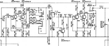
The input impedances in both stages shown is fairly high, so smaller caps were chosen as that was all that was needed to attain the desired frequency response.
You might want to avoid increasing the values of most of these caps as the charging time constants become excessively long which can affect operating point of those stages until the caps are fully charged. Smaller electrolytics tend to have somewhat better HF and small signal performance than larger value caps.
You may be able to replace these with low voltage films as well.
- Status
- This old topic is closed. If you want to reopen this topic, contact a moderator using the "Report Post" button.