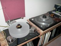
I had posted one already in here. it is use an old direct drive TT to drive with a elastic thread work perfect and don't cost too much on the top with speed control too, no bearing of power motor can compare to a direct drive platter and ratio 1 to 1 smooth and quiet, the only problem is need more spaceHi All,
I have been working on a TT design for some time now and I quickly realized that the most difficult step was designing a good drive system. As I have searched I have noticed that there are many people who are also looking for a good DIY turntable drive system, some to upgrade existing tables, some for new designs. There are some great ideas out there, but they are all over in different threads and sites, so I thought I'd start this thread that is specifically dedicated to TT drive systems.
Please, if you have ideas for DIY drive systems post them here. Maybe you have a schematic for a nice variable frequency drive (VFD) that could drive synchronous motors, or maybe you have a feedback system that could be used on encoded DC motors, or maybe you have some way of using old VCR drive motors. Whatever your plans, post your links, and share your idea here so everyone can benefit.
Also, if you are looking for a specific kind of drive system and need some help, post here and hopefully the collective knowledge of the followers of this thread can help.
I hope that this thread will become the "one stop shop" for those looking for TT drive systems.
Thanks for your contributions.
tony ma
Attachments
My take on how to drive a DIY Turntable
Hello everyone,
I originally joined this forum to do research on Tangential Tonearms and
to share the design of my own Tonearm. Having never participated in any
kind of forum, I havn't figured out yet how to do that. But after reading
all the suggestions as to how to drive a DIY turntable, it has become apparent that a simple way to do that would be to use a motor from a
used direct drive turntable as has been suggested by many others.
But instead of driving from a direct drive turntable to a DIY turntable with
a belt, why don't you take the extra step of removing the motor from the
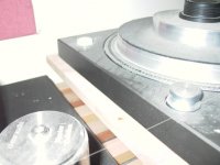
direct drive turntable and make a free standing housing for it in the Micro Seiki style? In addition, since the direct drive motors were not made to take a side load, I would add a bail or bracket to the top of the motor
so that the top of the spindle could be supported with a bronze sleeve
bearing. A number of years ago I obtained two direct drive motors from
Matsushita as samples to experiment with. but I never got around to that.
Yesterday I looked at the motors and found that the idea with the bail
is feasable. This approach would take up half the space and would look
pleasing to the eye. What do you think?
Ralf
Hello everyone,
I originally joined this forum to do research on Tangential Tonearms and
to share the design of my own Tonearm. Having never participated in any
kind of forum, I havn't figured out yet how to do that. But after reading
all the suggestions as to how to drive a DIY turntable, it has become apparent that a simple way to do that would be to use a motor from a
used direct drive turntable as has been suggested by many others.
But instead of driving from a direct drive turntable to a DIY turntable with
a belt, why don't you take the extra step of removing the motor from the
direct drive turntable and make a free standing housing for it in the Micro Seiki style? In addition, since the direct drive motors were not made to take a side load, I would add a bail or bracket to the top of the motor
so that the top of the spindle could be supported with a bronze sleeve
bearing. A number of years ago I obtained two direct drive motors from
Matsushita as samples to experiment with. but I never got around to that.
Yesterday I looked at the motors and found that the idea with the bail
is feasable. This approach would take up half the space and would look
pleasing to the eye. What do you think?
Ralf
Attachments
More
Hello everyone,
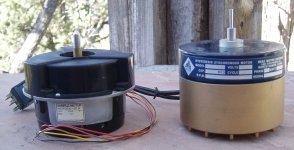
In addition to the direct drive motor, a capstan motor from a junked
professional studio tape recorder could be used. The attached picture
shows a Matsushita direct drive motor and a Beau capstan motor.
The direct drive motor woul need a support bearing near the top in my
opinion. The capstan motor would be ok as is because it was designed to take a side load. The capstan motor is "stubby" which would help to keep
a low profile in the overall appearance. Most of the capstan motors in
professional studio tape decks are much taller. That would be ok if one
were to design one of those tall turntables.
Ralf
Hello everyone,
In addition to the direct drive motor, a capstan motor from a junked
professional studio tape recorder could be used. The attached picture
shows a Matsushita direct drive motor and a Beau capstan motor.
The direct drive motor woul need a support bearing near the top in my
opinion. The capstan motor would be ok as is because it was designed to take a side load. The capstan motor is "stubby" which would help to keep
a low profile in the overall appearance. Most of the capstan motors in
professional studio tape decks are much taller. That would be ok if one
were to design one of those tall turntables.
Ralf
Attachments
I'm very interested in this thread and want to make my own TT, much moreso than other audio components, even though I have less mechanical skills and knowledge than of electronics.
There's an interesting thread here that may merit review, even though it has a bit of a negative title: "Why is DD bad?"
http://www.diyaudio.com/forums/analogue-source/71356-why-dd-bad-3.html
There's an interesting thread here that may merit review, even though it has a bit of a negative title: "Why is DD bad?"
http://www.diyaudio.com/forums/analogue-source/71356-why-dd-bad-3.html
Hurst motors....
after leaving the LYD42 Hurst motor running for a week and applying a little 3-in-1 oil (light machine oil) to the bearings as per George Merrill, I can safely say the motor is very quiet .The motor I chose is substantially more robust than those intended for turntable use.
I am mounting it in an Ariston 11s , at the (approximately) 7:30 position as per the Funk Firm and others. I have to say I am completely disappointed with the build quality of the Ariston. Linns are essentially the same thing, and I'd be even more disappointed had I paid for a new LP12...
Excellent! Good to hear that the hurst is working well for you. What are you using to drive your motor? You mentioned that you had thought about the MP3 source, but never what you actually decided to use in the end. I would love to hear what is working for you because my motor is very similar to the one you have.
Hurst suggests a .39 mF capacitor...
gtyler:
I haven't checked the speed but will do so most likely tonight. Based on Hurst's specs, the motor should run at 300 RPM. As the original motor had the same speed, it should all work out. The Ariston is not mine, so I am limiting the motor change to just the motor and cap...
In particular which motor do you have?
For a variable speed control, I intend to use mp3 tracks of 60 Hz, in stereo, 90° out of phase. I'll make several with +/- .06Hz, so that I can adjust the speed. Run the signal to a stereo amp (class D or whatever, but ---as per Mark Kelly, not an AB type). Then through a speaker transformer to up the voltage to 70 volts or so... and out to the turntable motor. The power from the amp will act as a power supply, so no need for a switch, but a fuse would still be a smart thing to include.
An alternative is to feed a small voltage to a few DC stepper motors...
The Ariston is not mine, so I am limiting the changes to just the motor and cap...
Hurst model number...and torque information.
I'm using the model LYD42115D. The 3001-001 "turntable motor" is from the same series, but has 1/2 the torque at the same speed. The LYD requires 4 Watts, whilst the "turntable motor" requires 1.8 Watts.
So a little more energy. but a lot more torque. As I stated one post ago, the motor is very quiet now. Originally it was quite nasty...
Hello Stew ,
Would this one work better , thoughts ? ...
T, TA Direct Drive Permanent Magnet AC Synchronous Motors
* 2601-001
* Item # Model T DD Synchronous Motor........ 98.51
Would this one work better , thoughts ? ...
T, TA Direct Drive Permanent Magnet AC Synchronous Motors
* 2601-001
* Item # Model T DD Synchronous Motor........ 98.51
I have a question.
I have this motor:
HURST 300 RPM SYNCHRONOUS MOTOR/STEPPER MOTOR - eBay (item 380176978259 end time Dec-06-10 16:48:45 PST)
And two of these transformers:
Antek - AN-0209
My plan, as i mentioned before, is to use an amplifier to boost the signal form an mp3 file that I have created to drive the motor. Then to use the transformers to boost the voltage to the required level for the motor. I have finally got all the components, and I would really like to try this motor out, however, when I first got everything together I gave it a try and it fried the amp that I was using. The amp was on it's way out anyway. It was having some severe problems, but it was working to drive a smaller stepper motor that I had. When I hooked it up to the transformers, and to the motor, it worked for about 5 seconds then it quit forever. It may have been my bad connections shorting or coming loose that caused it to blow, but I'm worried it was the load.
So what do you think? I have been told before that an amp should have no problem driving this setup, but I'm skeptical. If I get another amp am I just going to blow it too as soon as I hook it up? Do I need a more powerful amp or a different type of amp to drive this setup? Is there a way that I can measure the impedance of the motor and transformer assembly? Please let me know if you have any comments.
Thanks for all your help!!
I have a motor that I need some help with. I've had it for sometime and have always wanted to do something with it because it such a lunker.
I need some help hooking it up. Here's what the ID plate says....
Elinco Hysteresis Synchronous Motor
115vac.....1 phase........60cycle...... 1/40 hp
1800 rpm.....0.6 amps......Temp Rise 40° C
Cap Value 3 uF.......Cap Volts 220......Duty Cont
Insulation Class A
It has 4 wires
white w blue stripe
white w yellow stripe
white w red stripe
white w green stripe
I'd like to hook it up just to see if it's even in the ball park.
Anyone help with the wiring?
Using an AC motor, one needs to find something that can create a rock solid frequency.
Recent article in AudioXpress describes a method of dividing down a crystal, then using a switched cap low pass filter to derive a very stable sine wave -- the same general idea was described by Gary Galo in 1986 (Audio Amateur, predecessor to AX -- and cited a previously written article in Electronics World, I believe that was the publication). Linn LINGO seems to use 2 XO's for 33.3 and 45RPM.
The problem gets trickier if you want to listen to discs that were recorded when speeds were somewhat less standardized -- but you could do this with a DSP chip from ADI or TXN.
For direct digital synthesis there are chips such as this:
AD9833 | +2.3 V to +5.5 V, Low Power (20 mW), Programmable Waveform Generator in 10-Pin µSOIC Package | Direct Digital Synthesis ( DDS) & Modulators | RF / IF ICs | Analog Devices
At the stated max output frequency of 25MHz it has a frequency resolution of 0.00625Hz, which should be enough for most people - the frequency steps around 60Hz would be:
59.99375
60.00000
60.00625
...
and if that's not good enough resolution, just lower the input clock frequency and the steps drop in size proportionally. It needs a serial interface to set up the registers for the proper output frequency, easily done with a microcontroller, which can also be used to drive a display showing output frequency, or even scale it to show turntable speed in RPM.
Even a small microcontroller by itself can give a good crystal-based 60Hz sine wave with increments of 0.001Hz or smaller with the proper programming to implement a numerically controlled oscillator in software. A DSP for 60Hz is overkill.
Here's the Wikipedia articles, though they have much technical info but little in basic explanation - surely there are other web articles on the subject that explain the basics better - the idea isn't that complicated:
Direct digital synthesizer - Wikipedia, the free encyclopedia
Numerically-controlled oscillator - Wikipedia, the free encyclopedia
All the stuff about suprious signals and noise is for generating RF sines in the MHz or tens of MHZ range. At 60Hz some simple filtering will make a sine wave with less noise and distortion than one ever sees from the power line.
I have a motor that I need some help with.
Elinco Hysteresis Synchronous Motor
115vac.....1 phase........60cycle...... 1/40 hp
1800 rpm.....0.6 amps......Temp Rise 40° C
Cap Value 3 uF.......Cap Volts 220......Duty Cont
Insulation Class A
It has 4 wires
white w blue stripe
white w yellow stripe
white w red stripe
white w green stripe
I'd like to hook it up just to see if it's even in the ball park.
Anyone help with the wiring?
Yes.
Despite what the label says it's actually a three phase motor. The combination of the phasing cap and the winding inductance can be used to create two faked phases to run it on a single phase supply. An article which explains how this works without me having to type it is Here.
Motor performance is however vastly improved if it is run on a dedicated three phase supply.
I'm guessing that the four wires mean that the actual motor is star wired: looking at Fig. 1 there are four junctions that lead to the coils - one at the outer end of each coil and one in the centre of all three. You can confirm this by measuring the wire to wire resistance - there are 6 possible pairs of wires and three pair will show half the resistance of the other three pairs. One wire will be common to each of the first three pairs and it is the centre of the star.
,,
jackinnj, thanks for the information
I just got a copy of November's issue of audioXpress, where an AC turntable power supply has been presented using a 20.0 MHz microprocessor. This has a lot of appeal to me, a complete standalone solution. I'm certainly not an electronics designer (unlike Mark Kelly), nor have I ever pretended to be. I mainly work on the relatively (tweaky) simple mechanical side of things. I've developed patience when hunting down and isolating mechanical noises and aberrations, but haven't really delved into much digital, or electronics stuff. In the past I have, but I now have little patience for that side of things. I may have to re-develop that skill set.
jackinnj, as you suggest, using a faster running processor could provide more accurate adjustments, but only if I can validate the speed of rotation. A frequency generator and counter would make a lot of sense, but are not in my budget currently. I use a digital tach (+/- 0.05 RPM) to verify speed performance. My old Oracle has a stable speed (measured) of 33.4 RPM. This equates into a 0.2% speed error or .1 RPM, +/- 0.05 RPM. Better than I can hear.
The other solution that I have presented numerous times is the use of an mp3 player as suggested by Charles Altmann.
Both the frequency generator and an mp3 player require an amplifier , a trim pot somewhere, and a transformer of some sort. I do like the idea of microprocessor control though.
thanks again for the references
Yes.
Despite what the label says it's actually a three phase motor. The combination of the phasing cap and the winding inductance can be used to create two faked phases to run it on a single phase supply. An article which explains how this works without me having to type it is Here.
Motor performance is however vastly improved if it is run on a dedicated three phase supply.
I'm guessing that the four wires mean that the actual motor is star wired: looking at Fig. 1 there are four junctions that lead to the coils - one at the outer end of each coil and one in the centre of all three. You can confirm this by measuring the wire to wire resistance - there are 6 possible pairs of wires and three pair will show half the resistance of the other three pairs. One wire will be common to each of the first three pairs and it is the centre of the star.
,,
Checking this motor, my Fluke meter tells me that there are only two combinations that yield any resistance.
Blue-----Yellow 200 ohms
Green-----Red 58 ohms
not what I was expecting?
- Home
- Source & Line
- Analogue Source
- The Official Turntable Drive System/Motor Thread!