An externally hosted image should be here but it was not working when we last tested it.
An externally hosted image should be here but it was not working when we last tested it.
An externally hosted image should be here but it was not working when we last tested it.
An externally hosted image should be here but it was not working when we last tested it.
Congratulations
Good morning Records33,
that looks migthy impressive !
Can you give me some data about the weigth of the flywheel, the weigth of the actual platter (of the record player) and the size ?
And what is the exact purpose now: just for sharing this mouth watering execution of a flywheel or.......is it possible that we can "buy in" in this project ?
Currently my 17 kilogram platter is driven by a minute motor. The bearing and weigth of the platter make it serious stable. That is why i don't want a torque-heavy motor....it is so dominant....it will present itself (in the platter). A flywheel is a very good solution to detach the motor and platter. So i would be very interested.
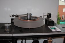
Included a picture of my current record player consisting of a oversized 50 centimeter platter (Scheu) with a diy tonearm (more than 17" !; based on a WTA).
Once again congratulations; and i will follow this thread closely.
Regards,
Reinout
Good morning Records33,
that looks migthy impressive !
Can you give me some data about the weigth of the flywheel, the weigth of the actual platter (of the record player) and the size ?
And what is the exact purpose now: just for sharing this mouth watering execution of a flywheel or.......is it possible that we can "buy in" in this project ?
Currently my 17 kilogram platter is driven by a minute motor. The bearing and weigth of the platter make it serious stable. That is why i don't want a torque-heavy motor....it is so dominant....it will present itself (in the platter). A flywheel is a very good solution to detach the motor and platter. So i would be very interested.
Included a picture of my current record player consisting of a oversized 50 centimeter platter (Scheu) with a diy tonearm (more than 17" !; based on a WTA).
Once again congratulations; and i will follow this thread closely.
Regards,
Reinout
Attachments
Good morning Records33,
that looks migthy impressive !
Can you give me some data about the weigth of the flywheel, the weigth of the actual platter (of the record player) and the size ?
And what is the exact purpose now: just for sharing this mouth watering execution of a flywheel or.......is it possible that we can "buy in" in this project ?
Hi, travel for several days, delayed response, please forgive me.
Air-bearing motor flywheel system weight 8.5kg, flywheel diameter is 140mm, the quality of 2.8kg.
Air-bearing motor flywheel system is designed for my reference Turntables, not sold separately, so sorry.
Thank you for your interest!
Reference turntable design drawings
An externally hosted image should be here but it was not working when we last tested it.
An externally hosted image should be here but it was not working when we last tested it.
 Very good !!!
Turntable operating procedures:
1. Start gas source controller power supply, pump to work. The air pressure reaches the set value, pressure sensor to work, the motor drive amplifier power automatically connected.
2. Turntables display default display 33.3 (speed).
3. Press START / STOP button to start the motor, turntable rotation.
4. The first time need to adjust speed. Speed test using the stroboscopic disc.
5. Press SPEED ADJUST button, the screen display is the motor speed, stroboscopic observation cell, the speed of recognition speed.
6. Press SPEED ± button, on the speed of coarse (coarse default state of each boot.) The display shows the motor speed, LED display 3 digits, coarse resolution of ± 1 rpm.
7. Speed stable, press PRECISION ADJUST ON / OFF button to turn fine-tune the speed of adjustment of status, the display shows the motor speed of 5 digits. And SPEED by SPEED-button fine-tune status, resolution ± 0.01 rpm.
8. Finished fine-tune the speed by SPEED LOCK button to lock the speed of data stored and the next boot speed to the default value of the last lock. (33 rpm and 45 rpm adjustment value can be stored separately)
9. Speed switching at 33RPM / 45RPM speed switching button.
10. By VACUUM ON / OFF button, the adsorption or release records.
11. According to the display the right DISPLAY ON / OFF button switches the display, you can choose LED digital display on and off.
An externally hosted image should be here but it was not working when we last tested it.
An externally hosted image should be here but it was not working when we last tested it.
An externally hosted image should be here but it was not working when we last tested it.
I have done a lot of work on magnetic thrust bearings and it was my intention to use one just as MiiB suggests. However, if the air-bearing that the OP is using is the same one I am thinking of then it has a motor built into it that also makes use of the air-bearing. In addition, there is the possibility that noise will be even lower as no radial support is required.
can you tell us something more about the motor control board ?
32-bit fixed-point motor control DSP controller as core processors, main frequency up to 150MHz. Have very good control system control precision and chip processing power. Drive the use of advanced permanent magnet DC servo motor control algorithm, implemented in digital form all the current loop, velocity loop, the closed-loop control.
Last edited:
Why not replace the air bearing on the flywheel with at magnet thrust bearing..??
simpler and just as effective...
I have done a lot of work on magnetic thrust bearings and it was my intention to use one just as MiiB suggests. However, if the air-bearing that the OP is using is the same one I am thinking of then it has a motor built into it that also makes use of the air-bearing. In addition, there is the possibility that noise will be even lower as no radial support is required.
Mr. YNWOAN described is correct. The air-bearing motor is no friction.
- Status
- This old topic is closed. If you want to reopen this topic, contact a moderator using the "Report Post" button.
- Home
- Source & Line
- Analogue Source
- Air-bearing motor flywheel