It is always interesting to visit the thread and see nice people with passion and perfectionism for that very very musical and involving sounding tt. I am in audio about 40 years and I had owned many good tts.No tt is compared with 124. I had used Dual 1019 idler wheel when I was very young, next an Era, after that the Ariston RD11,several Linn versions, Pink Triangle, Walker, Benz Revox , Kuzma Stabi, Micro Seiki BL 91, Thorens 150, 125, 126,EMT 928 , Aura from David Whitaker and my last was the Transrotor Apollo. All could not be compared to the musicality , PRAT, dynamics, emotional touch, liveness etc of the 124...that is and will be my last and best tt.
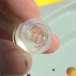
I will need to replace its bubble lever as it seems empty...How can I remove it without to cause any damage to its housing that is part of the chassis.. I think that if I could soften the glue that holds it by using alcohol or ?.. then it might be easier to remove it by pressing it?
If not thatsmoother way, have I to push it strong from out side to inside using a.. hammer?
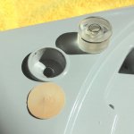
There is no glue holding the plastic bubble level in place. Rather a spring clip that fits in a machined groove near the top of it. The clip, which is circular and cut so that it isn't a complete circle, makes tension between the body of the level and the bore in the chassis where it fits into.
To remove the bubble level you pretty much need to disassemble most of the chassis. (how I do it) Then place bare naked chassis, face down into a padded surface so you don't damage the finish on your expensive TD124 chassis. Next you need a piece of hardwood dowel to fit through the hole in the chassis underside where the level fits. With said piece of hardwood dowel making contact with the bottom of the bubble leve, use a small light mallet to gently tap out the bubble level. It will tap out with small amounts of force.
To assemble the new bubble level in place, do reverse of disassemble.
It's easy. Just don't break any other part of the TD124 while doing this.
-Steve
Ps: source for replacement bubble levels..... Mirko, Simone Lucchetti, other sellers on ebay. etc. Mirko has supplied a couple to me that were exact replacements.
Hi ralphfcooke,
The yellowed that you have and works fine is the original and most are yellowed like your's. If mine was ok I would not touch it and not replaced it, as it would lose the originality.
On the other hand a new one would be nice , clear and maybe more accurate than the original. If a new replacement could be a very well made and more accurate, the way to remove the old one and replace it with that new one could be easy and safe, then I could do that.
But I must do that as mine is empty and does not work..
Maybe an idea to refill it without removing it and probably damaging it? What is the liquid to refill it? If i could drill it from underneath by using a very thin drill and press the recommended liquid so to be inserted inside it,and then to put a silicone adhesive so to close the small hole?
Thank you for any ideas
Hi Steve ,USER 510
Thanks a lot for your very informative advice and help.
It looks that a disassembly of most chassis parts seems to me quite difficult and stressful.
The first time is always like that.
So Steve is it needed to remove arm,platter,shaft ,and /or more parts?
I do not remember it from underneath. If the bubble level is visible , can I do all you kindly have advised me without to remove more parts of the chassis.
Thank you again
Hi Steve ,USER 510
So Steve is it needed to remove arm,platter,shaft ,and /or more parts?
I do not remember it from underneath. If the bubble level is visible , can I do all you kindly have advised me without to remove more parts of the chassis.
Thank you again
I usually replace the bubble level while performing a refurb to the rest of the motor unit. So it is normal for me to see the chassis minus its mechanical appendages.
For certain you'd need to remove the platters flywheel with brg shaft attached, upper platter and of course the tonearm. Tonearms are easy on the TD124.....unscrew the three M5 machine screws holding the armboard in place and, usually, that is all that is needed to lift the arm and arm board off the chassis alltogether. And find a nice safe out of the way place to park the arm and board in an upright position.
I'd use something to plug the bearing housing to keep its oil in and the dirt out. Because you will have the chassis upside down while pushing the old bubble level out.
That should be enough disasembly to replace the bubble level, I'd think.
Mirko for the new bubble level.
-Steve
In recent months I have serviced 4 different td124 units, and each of them presented a unique mix of problems to be solved. But it is the last one that I want to post about today.
The subject is my own td124 serial number 13943. E50 equipped. It has a new coil set from AudioSilente. The motor has received the customary CLA (clean, lube, adjust) and its rotor exhibits very long spin down times while not powered.
The problem was when I put power to it (115 vac @ 60 hz) that the motor exhibited low torque.....not enough to turn the platter.
In trouble shoot mode I first checked to see that the coils were getting adequate voltage. (At the voltage commutator.) I did this with a multi-meter while placing a probe at the red solder tab and the other probe at a black. (both red and black to the same coil) and with power on I read 56 vac. Not enough. I should be seeing full 115 volts. (Btw. Be careful when doing this as accidental electrocution may occur
Btw, I checked voltage at the mains and did measure 115 vac.
Thinking that the stator coil set should be ok (better than stock) I proceded to search for what was preventing full voltage from getting from the mains to my stator coils. I started with the on/off switch.
To check the switch it occurred to me that what I wanted to know was if the switch, in addition to interrupting the flow of current, was acting like a resistor and not allowing 'all' of the current flow to pass through it. Using the multi-meter again I checked across the switch for ohms. In the past I have measure .1 ohms on switches that were part of a healthy motor circuit. This one was measuring .6 ohms. So I disassembled the switch and cleaned all of the metal parts with acetone. The contact breaker was clean and free of sparking residue, but I washed that with acetone also. Reassembled the switch and conducted the ohms test again. This time I read .1 ohms. Good. That eliminates the switch
But the motor still was not getting 115 into its coils when resting the red and black solder tabs on the commutator. Still 56 vac.
Oh, btw, the neon strobe bulb had been lighting up with apparent strength through out.....and still was. And I had renewed the 33kohms resistor, which measured 33 kohms on the multi-meter.
next, I had to consider if the bulb holder, or the wires themselves were acting as a resistor.
The wires checked ok and looked good. But the bulb holder had an issue I had previously passed over; Of the two spring pins inside that create the circuit to the bulb, one of them had a crunchy action. I could realize this while pressing down on the pin with the eraser end of a wood pencil. Crunchy crunchy. Hmmm. There must be some history there, I thught to myself.
I ohms tested the bulb holder by inserting one multi-meter probe into the hole of the wire clamp and lightly screwed the set screw down to hold that probe in place . Then did same with the second post and probe. With the multi-meter set to measure ohms I placed a flat bladed screw drive across the two pins within the holder to create a short and get an ohms reading. The read was .5 ohms. Hmmmm. Add this to the crunch action of the one pin and it occurred to me that perhaps a little cleaning with acetone might be useful in improving this ohms read.
So I used a modelers paint brush and some clean acetone to dribble some acetone down into the bore and spring of the spring pin. I did this repeatedly while alternately pushing on the pin to work the acetone into the parts within.
You know these bulb holders are not built to be disassembled. The only way to take one apart is to destroy it. Hence my method.
Anyway I continued the acetone with lots of spring pushing to see if I could not clean the conducting surfaces within and get rid of the resistancee I was measuring.
As final touch I dribbled about 3 small globules of light silicone lube into the the pin and worked the action some more with my pencil erasor.
Then, finally, the test...... Multi-meter hooked up as before. This time the reading was .1 ohms. Wow. That's better, let's try it, I said.
Skipping the voltage test at the commutator, I just assembled the wires to the holder and the bulb into it. Assembled the strobe into the chassis as per design and ran the motor.
Guess what....? The motor now had much more torque.! Problem solved?
Well It's running strong now. On a summer morning cool start up I have 33-1/3rd on the strobe within the first rev!
After that, some pitch adjust while all of its drive train parts get up to operating temp...
For future reference my take is to test voltage going into the coil just to see that a switch, a bulb holder, or even a wire isn't acting like a resistor.
-Steve
Dear Steve
Thank you for your info yes these switch can give problems first thing I do is clean these contacts with a fiberbrush or replace the switch with a new one they used in earlyer TD124 tables .I had no problems with the bulb holder but often I replace the complete wiring inside the table .
Volken

I usually replace the bubble level while performing a refurb to the rest of the motor unit. So it is normal for me to see the chassis minus its mechanical appendages.
For certain you'd need to remove the platters flywheel with brg shaft attached, upper platter and of course the tonearm. Tonearms are easy on the TD124.....unscrew the three M5 machine screws holding the armboard in place and, usually, that is all that is needed to lift the arm and arm board off the chassis alltogether. And find a nice safe out of the way place to park the arm and board in an upright position.
I'd use something to plug the bearing housing to keep its oil in and the dirt out. Because you will have the chassis upside down while pushing the old bubble level out.
That should be enough disasembly to replace the bubble level, I'd think.
Mirko for the new bubble level.
-Steve
Steve is the height from these replacement bulb also 12mm or the often seen 9mm ?

On my 124/II the bubble level was not held in place by adhesive. A metal spring clip holds it in place. This clip sits in a groove on the bubble level and is located very close to the top of the level. Beneath the level is a circular piece of coated paper. I removed the level by first heating the chassis to help expand it a bit, then using a wide diameter punch to gently tap through the chassis hole on the underside.
Attachments
Steve is the height from these replacement bulb also 12mm or the often seen 9mm ?
12mm. Well there was no difference in height standing side by side and the replacement level had the same chamfered edge on top as the original.

The replacement level can be seen in this partial assembly.
-Steve
Dear Steve
Thank you for your info yes these switch can give problems first thing I do is clean these contacts with a fiberbrush or replace the switch with a new one they used in earlyer TD124 tables .I had no problems with the bulb holder but often I replace the complete wiring inside the table .
Volken
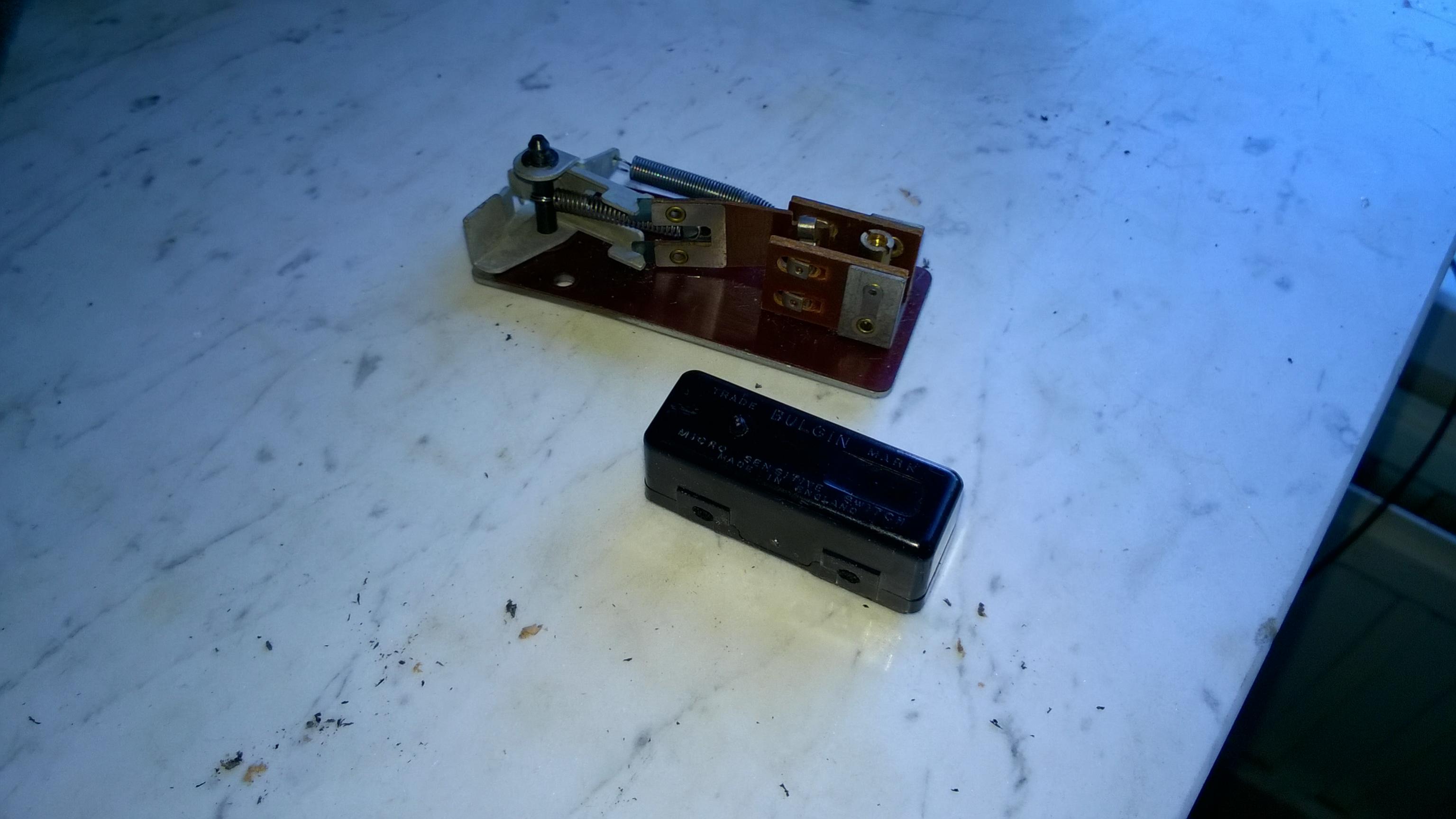
The external switches are easier to deal with. The earlier 'Bulgin' switch requires disassembly. But it is simple; just press the pin through and the switch disassembles completely in your hands.
The bulb-holder issue was a wierd one for me. It wasn't until I noticed the crunchy action in the one spring pin that I had a clue. I'm guessing there might still be an oem replacement for this part somewhere in a thick catalog of parts. My reason for hope is that we can still find a replacement neon bulb, so why not the bulb holder!
-Steve
user510 - Steve, just wanted to thank you for pointing out the significance of the switch and bulb holder to achieving proper operation of the motor. It's not something I would have thought of and does beg the question, how many reports of motors lacking torque or not coming to speed at all might be attributable to corrosion in these components. Some accounts, if I recall correctly, may have mentioned test wiring the motor directly, but certainly not all. Your experience suggests even if the motor appears to be operating properly, spending some time on these components is still a good idea. Thanks for the info.
more switches and bulb holders content
with reference to my previous post re: switches and bulb holders, I took some time to draw a voltage map of the mk 1 scheme. I know there have been a few other maps presented, but I wanted to toss mine into the mix, if Keven allows...
Large file size. This photo is linked from my web page and will remain there so long as I keep paying the bills to my web host.
http://www.theanalogdept.com/images/spp6_pics/TD124%20notes%20and%20data/TD124%20voltage%20map.jpg
-Steve
In recent months I have serviced 4 different td124 units, and each of them presented a unique mix of problems to be solved. But it is the last one that I want to post about today.
The subject is my own td124 serial number 13943. E50 equipped. It has a new coil set from AudioSilente. The motor has received the customary CLA (clean, lube, adjust) and its rotor exhibits very long spin down times while not powered.
The problem was when I put power to it (115 vac @ 60 hz) that the motor exhibited low torque.....not enough to turn the platter.
In trouble shoot mode I first checked to see that the coils were getting adequate voltage. (At the voltage commutator.) I did this with a multi-meter while placing a probe at the red solder tab and the other probe at a black. (both red and black to the same coil) and with power on I read 56 vac. Not enough. I should be seeing full 115 volts. (Btw. Be careful when doing this as accidental electrocution may occur
Btw, I checked voltage at the mains and did measure 115 vac.
Thinking that the stator coil set should be ok (better than stock) I proceded to search for what was preventing full voltage from getting from the mains to my stator coils. I started with the on/off switch.
To check the switch it occurred to me that what I wanted to know was if the switch, in addition to interrupting the flow of current, was acting like a resistor and not allowing 'all' of the current flow to pass through it. Using the multi-meter again I checked across the switch for ohms. In the past I have measure .1 ohms on switches that were part of a healthy motor circuit. This one was measuring .6 ohms. So I disassembled the switch and cleaned all of the metal parts with acetone. The contact breaker was clean and free of sparking residue, but I washed that with acetone also. Reassembled the switch and conducted the ohms test again. This time I read .1 ohms. Good. That eliminates the switch
But the motor still was not getting 115 into its coils when resting the red and black solder tabs on the commutator. Still 56 vac.
Oh, btw, the neon strobe bulb had been lighting up with apparent strength through out.....and still was. And I had renewed the 33kohms resistor, which measured 33 kohms on the multi-meter.
next, I had to consider if the bulb holder, or the wires themselves were acting as a resistor.
The wires checked ok and looked good. But the bulb holder had an issue I had previously passed over; Of the two spring pins inside that create the circuit to the bulb, one of them had a crunchy action. I could realize this while pressing down on the pin with the eraser end of a wood pencil. Crunchy crunchy. Hmmm. There must be some history there, I thught to myself.
I ohms tested the bulb holder by inserting one multi-meter probe into the hole of the wire clamp and lightly screwed the set screw down to hold that probe in place . Then did same with the second post and probe. With the multi-meter set to measure ohms I placed a flat bladed screw drive across the two pins within the holder to create a short and get an ohms reading. The read was .5 ohms. Hmmmm. Add this to the crunch action of the one pin and it occurred to me that perhaps a little cleaning with acetone might be useful in improving this ohms read.
So I used a modelers paint brush and some clean acetone to dribble some acetone down into the bore and spring of the spring pin. I did this repeatedly while alternately pushing on the pin to work the acetone into the parts within.
You know these bulb holders are not built to be disassembled. The only way to take one apart is to destroy it. Hence my method.
Anyway I continued the acetone with lots of spring pushing to see if I could not clean the conducting surfaces within and get rid of the resistancee I was measuring.
As final touch I dribbled about 3 small globules of light silicone lube into the the pin and worked the action some more with my pencil erasor.
Then, finally, the test...... Multi-meter hooked up as before. This time the reading was .1 ohms. Wow. That's better, let's try it, I said.
Skipping the voltage test at the commutator, I just assembled the wires to the holder and the bulb into it. Assembled the strobe into the chassis as per design and ran the motor.
Guess what....? The motor now had much more torque.! Problem solved?
Well It's running strong now. On a summer morning cool start up I have 33-1/3rd on the strobe within the first rev!
After that, some pitch adjust while all of its drive train parts get up to operating temp...
For future reference my take is to test voltage going into the coil just to see that a switch, a bulb holder, or even a wire isn't acting like a resistor.
-Steve
user510 - Steve, just wanted to thank you for pointing out the significance of the switch and bulb holder to achieving proper operation of the motor. It's not something I would have thought of and does beg the question, how many reports of motors lacking torque or not coming to speed at all might be attributable to corrosion in these components. Some accounts, if I recall correctly, may have mentioned test wiring the motor directly, but certainly not all. Your experience suggests even if the motor appears to be operating properly, spending some time on these components is still a good idea. Thanks for the info.
Appreciated. One thing about testing a motor off the chassis with a direct hook-up is that it avoids using the switch and bulb...so that doesn't take into account these two variables.
It certainly makes the owner feel better when the TD124 is operating at its full potential.....and the motor is such a huge part of this.
-Steve
Steve, with reference to your drawing (let's post it here permanently if OK with you) the black and blue wires where they connect to the socket are the most likely culprit. I usually clean up and sometimes replace the wires if they are too corroded.
Sure. I'm happy to offer it. I posted the larger drawing because it prints out letter size with decent resolution. A color printer is preferred.
I guess the real thing to inspect is voltage going into the coils. If it is +/- a couple of volts from mains, good. If its quite a bit lower, then it is trouble-shoot mode.
-Steve
I was talking with a friend who is rebuilding TD 124s, but is not following this thread and mentioned some members were trying to track down a suitable replacement for the strobe bulb holder. He said he'd found one and gave me the link. As I don't recall the rules on direct links to sellers, I'll say it's an eBay seller zappytiger and it's listed as "SATCO Double Contact Bayonet Socket Lamp Holder BA15D Steel Base 120V 500W" Hope that can help someone. He's also found what he believes are equivalent strobe bulbs that are quite inexpensive.
I was talking with a friend who is rebuilding TD 124s, but is not following this thread and mentioned some members were trying to track down a suitable replacement for the strobe bulb holder. He said he'd found one and gave me the link. As I don't recall the rules on direct links to sellers, I'll say it's an eBay seller zappytiger and it's listed as "SATCO Double Contact Bayonet Socket Lamp Holder BA15D Steel Base 120V 500W" Hope that can help someone. He's also found what he believes are equivalent strobe bulbs that are quite inexpensive.
It's an easy google search to find the ebay page with this lamp holder for sale. It is not an exact replacement. It lacks the two posts with set screws that the original lamp holder has. But it's close and could likely be made to work with a little disassembly and soldering, I think.
Yes, there are replacement neon bulbs available. I posted this a couple of years back. This thread is been running long enough that much of its info is buried deep within. The replacements I found I was able to purchase off ebay at around $5.00 each. I recall an ebay seller in Spain was selling this bulb at $20 each. I bought one of those, researched the catalog number printed on the bulb and found the bulbs available off ebay at the $5 dollar price noted above.
-Steve
Steve he also passed along a page from autoelectricsupplies.co.uk with this one BA15D - PARALLEL PINS. Looks more like what you're describing.

That looks closer. Cool!
I notice the seller seems to specialize in Automotive parts. We need to know if the bulb holder can handle 250 vac as well as the normal 12 vdc used on autos.
Nice info.
-Steve
Last edited:
- Home
- Source & Line
- Analogue Source
- Restoring and Improving A Thorens TD-124 MKII