It could be 3/16 imperial at 4.7625 adapted. I have a Papst industrial motor at 6.3 mm. I speculate it fits 1/4 inch at 6.35 oilite outer bearing. The bearing dark so not oilite really. Sometimes cast iron which is excellent if used correctly. The oil needs some room, 0.05 mm is 0.025 slop. < 0.001", it looks possible although large. Papst might have use the clock makers trick and slightly compressed the oilite bearings on a preset press. Be warned you can not ream them if going too far. Books say it can be done. It never worked for me. Go very very slow if you do. You can use a shaft as press limiter.
The motor I designed uses Swiss exact 6 mm shafting ( super hard, super finish, ). The oilite also 6 mm stated. The cost of the shaft is silly money and the oilite 50 cents. Even so the 6 mm oilite as sold is an exact running fit every time and if anything the better component. These motors are very very fussy. I think the 3/16 " pressed will be correct. As you can see the pressed size once correct will make the same part every time. Oilite is made in a die so always the same in all directions. Even the cheapest shafting is 5.995. I made some volume and switch extenders using air fittings much like plumbing parts recently. Reamed with a 6 mm drill ( someone lost the reamer ). Excellent is the least I can say. The bore was 5 mm before reaming with 5.995 aluminium shafting. Was made is 10 minutes at a fraction of the usual cost. The reaming in a drill press.
You can always fit new oilite cylinder bearings into eyeball types. First drill 4 oil ways accross the existing barrel shape. Then ream to take the oilite cylinder. Press fit it by hand. The felt pads will take enough oil to the new component to work. The reaming will stop flow from old to new so the oilways take over. I won't pretend it is easy. You can tell when the oilite is right. When oiled the slop will be almost zero and no resistance to rolling in the fingers. Sewing machine oil if that's all you can get is OK. When the motor is hot tap the shaft with a piece of wood to centre the bearings ( Garrard factory advice ). The Thorens motor is a bit tricky. It sometimes comes apart. If so loosen everything and get it to run. Tighten and tap to centre all parts. Take the motor apart carefully as it can save time later. The Garrard is less fussy. Too tight can be a problem. Too loose can give buzz ( mains harmonics ).
Here is a clearance caculator.
Bearing size and tolerance calculator - Bowman International Ltd. Bearing Calculator
Guessing the loading at 200 g and saying 6 x 10 mm I get
Oilite 5.999-6.014
Shaft 5.978-5.990
Tight = 0.009 mm ( 0.23 thou )
Loose = 0.036 mm ( 0.91 thou )
As the shafting I use is 5.9999
Tight = <0
Loose = 0.014 ( 0.36 thou )
Strangely every oilite tried was OK. The speed variation we get must be that. I suspected rotor to stator field strengths. 501 has a small variance. Rumble is consistant at - 79 dB weighted ( Thorens coupler ) showing that the bearings do a good job. The Garrard is direct coupled so any error is horrible in terms of noise. I suspect a TD124 about - 65 dB, which is fine. The best records ever pressed about - 74 dB.
As you can see the Garrard 501 is a world record for idler drive rumble. Few belt drives get to - 79 db. It is debatable if -90 dB will be of advantage. The turntable in question far more expensive and to my ears not as good as a TD124 even. Bland and slightly sterile. Hard to say because sometimes that is how it's set up.
referenced to what level?...... The best records ever pressed about - 74 dB. .......
I would like that also. The test house is just closing in Germany. The 501 was rushed there for last minute testing. The sample we made years ago and now are the same.
acuhorn Garrard 501 Time machine
Here is the review to unpick. The Thorens method is well known. The -74 db we got on a test record is the limit of real world testing in this German test house ( Part of Mercades ). It might interest people to know the standard 401 design of main bearing can work to this level. The noise of a 401 is all motor. If you have any sense no ceramic balls please. The 401/301 shaft is to 55 Rockwell ( C ) and will last about two weeks ( LP12 to 64 I think 501 also ) . Some guy adds a nylon disc ( or PTFE). That would be worth a thought.
I have no conection with the marketing of Garrard. All I did was suggest ways this figure could be reached. The motor is my design although based on the Garrard - Throens type.
Rumble is highly questionable as a test. The unweighted should be included as it will colour the sound. In the distant past German magazines had Garrard 301 as - 15 dB. When I asked how come I was told it was a subjective reading. - 35 db unweighted I will believe. The 301 did less well when stereo arrived. The 401 is better but lacks verve. The 501 betters them both yet sounds like a 301. This was important to me as I wondered if 301 was about vibrato. It isn't. The 501 sounds like an even more powerful 301 and less like a 401/124. I have a 401 myself. The 501 motor is about 250% the size of 301/401/124 motor size. Full voltage is not used until 78 RPM. This allows the inductance of the motor to be factored in whilst not exceeding limits. If you like an engine with no gearbox. It has a SVF oscillator of good stability. No eddy current brake needed. That is worth trying on TD124.
I would like that also. The test house is just closing in Germany. The 501 was rushed there for last minute testing. The sample we made years ago and now are the same.
acuhorn Garrard 501 Time machine
Here is the review to unpick. The Thorens method is well known. The -74 db we got on a test record is the limit of real world testing in this German test house ( Part of Mercades ). It might interest people to know the standard 401 design of main bearing can work to this level. The noise of a 401 is all motor. If you have any sense no ceramic balls please. The 401/301 shaft is to 55 Rockwell ( C ) and will last about two weeks ( LP12 to 64 I think 501 also ) . Some guy adds a nylon disc ( or PTFE). That would be worth a thought.
I have no conection with the marketing of Garrard. All I did was suggest ways this figure could be reached. The motor is my design although based on the Garrard - Throens type.
Rumble is highly questionable as a test. The unweighted should be included as it will colour the sound. In the distant past German magazines had Garrard 301 as - 15 dB. When I asked how come I was told it was a subjective reading. - 35 db unweighted I will believe. The 301 did less well when stereo arrived. The 401 is better but lacks verve. The 501 betters them both yet sounds like a 301. This was important to me as I wondered if 301 was about vibrato. It isn't. The 501 sounds like an even more powerful 301 and less like a 401/124. I have a 401 myself. The 501 motor is about 250% the size of 301/401/124 motor size. Full voltage is not used until 78 RPM. This allows the inductance of the motor to be factored in whilst not exceeding limits. If you like an engine with no gearbox. It has a SVF oscillator of good stability. No eddy current brake needed. That is worth trying on TD124.
Interesting discussion I think they used the DIN 45545 Gleichlauf-Mess-Schallplatte there is no reference indication on this record I think its 5.42cm/sec can check it later.
Concerning the rumble measurements on the 501 and the influence from the motor the first spectrum shows the rumble measured in 1999 by German Audio magazine both with messkoppler .
The horizontal resolution from the AP is not high enough to be able to read the exact frequencies.
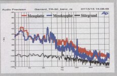
Problem with this measurements by messkoppler stays the cartridge/tonearm resonance influence on the measurements .
I use higher accuracy vibration measurements in addition to the standard W @ F measurements
Motor freq.about 24 hz at -40 db Motor Vibration 2xfl at about 100hz -73db.
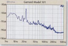
Later version the Transcription Reference in 2015 ,blue spectrum messkoppler, motorfreq. about 25 hz now at -48db Motorvibration 2xfl about 105 hz -70db
<snip>
Strangely every oilite tried was OK. The speed variation we get must be that. I suspected rotor to stator field strengths. 501 has a small variance. Rumble is consistant at - 79 dB weighted ( Thorens coupler ) showing that the bearings do a good job. The Garrard is direct coupled so any error is horrible in terms of noise. I suspect a TD124 about - 65 dB, which is fine. The best records ever pressed about - 74 dB.
As you can see the Garrard 501 is a world record for idler drive rumble. Few belt drives get to - 79 db. It is debatable if -90 dB will be of advantage. The turntable in question far more expensive and to my ears not as good as a TD124 even. Bland and slightly sterile. Hard to say because sometimes that is how it's set up.
I would guess -65dB to be in the range for a well tuned 124, still my experience is that when I hear rumble it is always built into the recording. My 124MKII is mounted on a heavy multi-layer slate plinth and the motor is mounted on Jaap's springs.. I am using a rare antique OEM belt which does make a difference to how quietly the table runs. I have a vague recollection of doing better than -70dB on track 6 (unmodulated) with the analog productions test record referenced to the 1kHz reference tone on track 1. As I recall the dominant noise source was the motor at around 120Hz, refer to Jaap's captures for what is possible with a 124.
Something to note is that this table is powered by a crystal referenced source at 60Hz with about 0.2% distortion at an invariant 110Vrms. (The main contributor to the distortion is the step up transformer, the output of the amp is 0.03%)
Nigel thank you for your contributions and the comparisons to the 501 which I am familiar with. Gives me a frame of reference.
Once I complete some other work I am going to get back to the Papst 3 phase project, I expect that to be quite illuminating.
That seems about right. As we discussed earlier the rotaion at light loading of the motor is about 1425 RPM @ 50 Hz. The platter rim is 10.5 inches like the 401. The shaft 6 mm . The gearing is 10.5x25.4/6 = 44.45. That's 44.45 x 100/3 ( 33.33 ) = 1481.67RPM. This requires about 52 Hz. We started with 6.33 mm and 5 mm shaft. This simple change helps wow. The only problem is a beat between 50/52 Hz in the power amplifer stage. There might be slip between idler and platter. I doubt it is much.
1482.67/60 = 24.7Hz
52 Hz shows as 104 Hz.
Idler = 2.22 Hz
The idler is about 66.7 mm ( used one ). This is a ratio ( not gearing ) 66.7/6 = 11.117 . 1482.67/11.1167 =133.4 RPM = 2.22 Hz. 301/401 will be close. Usefully low.
The TD124 is 80 mm I think. No idea of the rotational speed.
Viewed on a scope this looks like an AM radio waveform albeit the carrier is only 104 hz. One problem Linn Valhalla had is it's PSU ripple was hidden under the generated waveform at - 41 dB. Changing the Valhalla caps from 47 uF to 220 uF 250V helps. When on a floating supply of either 220 or 110 V the Valhalla is at - 60 dB which is not bad. Much of the Lingo upgrade was only that. Otherwise Valhalla is a good device. Phase shift to blue phase can be better on Valhalla ( select 0.22 uF ) . I am using a LP12 at the moment. It is hard not to like it. Yes it has these upgrades. The USA 60 Hz shows this clearly.
The TD124/301/401 motor is a rotating transformer. The solidity of the shaft to oilite bearings is the big question. It must be just loose enough to work and be free running.
The TD124 should be able to do it. I would mount the TD 124 motor to the plinth bottom. It might get you 3 dB. Make a cardboard template to say you are where you were. Doubtless this will be more complicated than it seems. The early 501 got - 69 db. I was over the moon. The idler system almost says this is impossible. It's almost like saying put the stylus on the motor. The 501 idler in new old stock Garrard in the test sample I think.
Martina I think was hoping for - 84 dB. I was rather surprised she didn't get something as the idler is now a jeweled bearing. I had a hunch it wouldn't change much. There comes a time when the ears must take over, she is pleased with the jeweled type. The Stardard Garrard is about 80 Rockwell ( C ) thrust made of simple spring steel. The hardness is like a hacksaw blade. It seems it is good enough. Spring steel can be very flat .
Martina I think was hoping for - 84 dB. I was rather surprised she didn't get something as the idler is now a jeweled bearing. I had a hunch it wouldn't change much. There comes a time when the ears must take over, she is pleased with the jeweled type. The Stardard Garrard is about 80 Rockwell ( C ) thrust made of simple spring steel. The hardness is like a hacksaw blade. It seems it is good enough. Spring steel can be very flat .
<snip>
The TD124/301/401 motor is a rotating transformer. The solidity of the shaft to oilite bearings is the big question. It must be just loose enough to work and be free running.
This is a good point and why I have struggled with the motor bearings, it seems not badly worn OEM motor bushings still seem to provide the best performance. I need to try some bushings made by Simone, at this point I do not trust any of the U.S. sellers of these parts, as they say in the U.K. they are "duff" - I have had problems with them seizing, fortunately no damage.
I would swag that for acceptable performance a new bushing would have to have an ID of < 4.9mm which would be consistent with my shaft measurement of around 4.7mm on the Papst at least. Unfortunately I do not have any pin gauges (metric or otherwise) so I have no means to verify this with any degree of accuracy. Next time I am working on one of these motors I will measure the shaft diameter, it cannot differ much from the Papst since they both use the same pulley.
I calculated the drive ratio of the 124 at some point (it is in here somewhere) and of course because of the intermediate belt it can vary significantly. The motor running speed would be typically at least 3% below nominal unloaded speed if the +/-3% stated speed adjustment range is to be believed.
Something to note is that this table is powered by a crystal referenced source at 60Hz with about 0.2% distortion at an invariant 110Vrms. (The main contributor to the distortion is the step up transformer, the output of the amp is 0.03%)
That's very good. I added a lot of feedback and did not get the reduction in distortion I exspected. Also by calculation the no feedback version was rather good. My late brother made a suggestion. The initial transformer I used wasn't very good. This might in itself cause feedback of some sort due to coupling. As distortion is vibration ( not really if second harmonic as it is in phase, if 1 % second only it could be alright ) low is good. One day I will take a dead 401 motor and wind it for 20 VRMS. A Hypex UCD 180 might like to try that. Or a Quad 405 module. Take your pick. It would allow thick wire which is very easy to hand wind. 4 x EL 34 with resistor safety balast could directly drive the motor I suspect. Not least in 110 V setting. GU 50 also.
I used a really good EI cored transformer rated at 50VA and designed for 50Hz operation, the amp can deliver 100W, and I am running a 15VA load so everything is running rather conservatively.
The thing runs open loop so I just adjust for the desired output voltage under load, interestingly the motor current does not vary appreciably over time, I guess it is so lossy it doesn't really notice changes in load.. lol
I have a newer version that includes about 20dB of feedback to improve voltage regulation and lower source impedance. I've not built one of these yet, finding someone to do the PCB layout has been problematic as I am not motivated to do it myself.
The feedback isn't always easy. I centre taped to ground the output then ran one side to the amplifier feedback input ( - ). This seemed easiest and tilted the results the way I wanted them. The original feedback was retained to aid DC stability and adjusted to suit . I gradually got the balance right. I didn't have too much trouble with oscillation. I wound a coil on my toroid. To be honest it didn't gain me anything. It was very easy to do. It was very interesting to view the distortion at the amp output to correct the load. Much higher than I exspected. Not like inside a tube amp on a resistor load. I suspect the amp was correcting compound distortion of transformer and load. That would be less likely if direct coupled to be seen. Something to say. People assume a low distortion when a speaker is driven by a low impedance amp. I suspect that might be more complex than thought. Insert 0R1 and measure the distortion across the resistor. If this is important I couldn't say. Someone said they got a very low distortion waveform driving a synchronous motor. The way that motor works suggests to me unlikely. If so a 1K resistor should make the motor vibrate badly as the waveform due to load is at >10 % THD. I seem to remember when I tried it the vibration was less ( as you might imagine ). If that distortion is real the vibration would be less. When that motor is used as a generator the waveform is the same into lets say a 1 watt load.
Interesting, I took a slightly different approach, I concluded it would be easier to include the power amp and transformer inside the feedback loop of a independent op-amp, this allows me to tailor the amount of feedback, and the open/closed loop response of the network based on what I felt I needed with a given motor and transformer combination, it is also quickly defeated.. Have not yet tested it, but the simulations looked OK into a variety of loads. One of these days I will build one. (I need another anyway)
I think 0.2 % is an excellent benchmark. It possibly is best to take distortion as vibration at the motor when the distortion is that low. A contact microphone perhaps. Look for higher frequencies. Voltage will be a big factor. As the TD124 has a belt the results will favour higher voltage where vibration will be higher. The point to make is the least vibration for the torque required. You can measure the distortion in the motor due to saturation etc. A series resistor within the range of the measuring equipement will show it, measure mV if you can and solder the BNC cable coax onto the resistor to avoid over voltage. It is not a 100 % imformative way to do it as I am sure someone will say. All the same it shows what's really happening or trends. My custom transformers saturate at >270 V ( 135 ). They are noisier as a result so I pot them.
The series resistor can help the motor. It isolates it to allow it to do it's own thing. It's not exactly current drive, but hints at it. It you think about it the motor doing anything new implies higher order harmonics could result. Not a good thing. The simple test is given the same voltage at the motor is the vibration by ear of the motor softer with a series resistor? This is a slightly incorrect idea as the motor will slow under transient load due to the resistor. A compromise can be had. The drag of the oil will minimise the resistor compromise and the eddy brake also. The resistor is if you like backlash.
I did build a RC filter for the 301. It was two transformers with the low voltage sides conected together ( 15 and 9 V perhaps ). The filter caps were nonpolar in 33 uF range or larger ( fo = 100 Hz ) . First attempts made for hot components. I think factoring in the inductance was too difficult. It's a shame I lost my notes as it was half sucesssful. I supect the usual 4 % THD with harmonics to 1 kHz was reduced to 1% which was mostly second harmonic. If you like passive a subwoffer filter at 230 V. One thing I did build in this experiment was a CVT by accident . Sure enough using feedback of the spare secondary worked. It got very hot. A magnetic amplifier would be workable if time was taken. Oneac is the best if you find one on ebay.
One way I tried was to make the op amp style power amp typical of Douglas Self that was unity gain stable. This proved to be easy enough. The increase was by addition of 100 pF to the dominant pole capacitor ( 33 pF ). That was a total surprise it was that small. The amplifier was higher gain than usual to encourage stability. At 50 Hz that will be OK. I also had a 72 Hz filter in the feedback loop. This is the advantage of building from parts. The amp even worked on tag strip. I lost my notes so can not remember it all.
The TD124 should be able to do it. I would mount the TD 124 motor to the plinth bottom. It might get you 3 dB. Make a cardboard template to say you are where you were. Doubtless this will be more complicated than it seems. The early 501 got - 69 db. I was over the moon. The idler system almost says this is impossible. It's almost like saying put the stylus on the motor. The 501 idler in new old stock Garrard in the test sample I think.
Martina I think was hoping for - 84 dB. I was rather surprised she didn't get something as the idler is now a jeweled bearing. I had a hunch it wouldn't change much. There comes a time when the ears must take over, she is pleased with the jeweled type. The Stardard Garrard is about 80 Rockwell ( C ) thrust made of simple spring steel. The hardness is like a hacksaw blade. It seems it is good enough. Spring steel can be very flat .
I have done this the motor mounted on a bottom plate ,Verdier in 1980 was the first one who did this, gives some improvement but its very difficult to decouple the motor vibrations from the bottom plate , tried also sinking them with lead etc.But the simple spring decoupling works a lot easier and with better results.
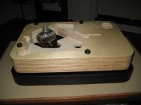
I think -84 db is not realistic the main vibrations are stil the motor, and idlerwheel good seen in the spectrum and forget not the modulation from the 2,2 hz idlerwheel vibration on motor frequencies 23 hz and 100hz.
Thorens TD124 got some more by the use from the steppulley extra bearing and steppulley vibration.
A plain and roundness idler is difficult to make and bearing offcourse jeweled sounds like watchmakers bearings .
Try to get contact with German Audio mag. asking which testrecords they use the DIN records are no longer available the usability of this testrecords is limited by wear.
You and I know that. Martina didn't. I was being a bit poetic. The motor shows through in the graphs, idler bearings will not cure that. - 84 dB in deflection terms is so small as to be well inside the wavelengths of visible light if Julian Vereker was right. He said 0.001" - 60 db is 0.000001" ( mono groove width ) . If the 501 is to be direct coupled then even - 79 db seems impossible. The TD124 should be much better than it is. I suspect the belt is not being allowed to work as it could. I wouldn't be surprised if TD124 would be better than anyone who owns one knows in terms of rumble.
Thorens TD124 Garrard 501 speed spectrum
Motor vibration 2xfl at 100Hz , with a span from 500Hz the peak is sharper !
Thorens TD124 with Papst motor spring motor decoupling span 400 HZ
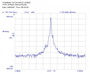
Thorens TD124 with E50 motor spring decoupling span 400hz
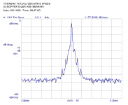
Thorens TD124 with E50 motor rubber decoupling span 400 hz
View attachment Thorens TD124.2 Speed spectrum rubber motor decoupling.bmp
Garrard 501 speedspectrum span 500hz !!
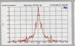
Motor vibration 2xfl at 100Hz , with a span from 500Hz the peak is sharper !
Thorens TD124 with Papst motor spring motor decoupling span 400 HZ

Thorens TD124 with E50 motor spring decoupling span 400hz

Thorens TD124 with E50 motor rubber decoupling span 400 hz
View attachment Thorens TD124.2 Speed spectrum rubber motor decoupling.bmp
Garrard 501 speedspectrum span 500hz !!

- Home
- Source & Line
- Analogue Source
- Restoring and Improving A Thorens TD-124 MKII