Experimental Drive 2
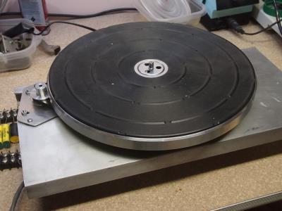
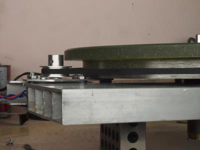
My first attempt was designed to fit inside the platter idler ring. It required the special pulley which was a PITA because it had to mate to the bottom of the spindle flange yet clear the spindle well flange. Then it had to rise up to clear the Mk II motor mount. I got to thinking that perhaps the outside of the platter idler ring could act as a pulley. I wasn't about to cut into my Thorens chassis, thus the aluminum extrusion. The new motor pulley is about twice the diameter of the first one. Out of sheer luck the I got it to almost perfect size the first try. It hits speed in about 1/4 turn compared to a full turn on X drive 1, even though the belt is 30% narrower and thinner. This is due, I suppose, to the larger pulleys putting less stress on the belt. I'm thinking that perhaps the motor more powerful than necessary.
The drive is really quiet. However, since it is a permanent magnet motor there is vibration due to cogging. I suspect a weaker motor would have weaker magnets and lower vibration levels. This is a 300 RPM motor. Perhaps 600 RPM would be a better choice. The motor pulley would return to the smaller size and the higher RPM might give more torque for the same size motor.
I'm preforming these experiments, not to replace the drive on my TD 124, but to test out ideas for a DIY turntable with features borrowed from Thorens, namely retro design cast aluminum chassis, similar bearing, cast iron platter and improved cueing.
The cast iron subplatter is one of the most beloved features of the TD 124. The vast majority of cartridges have no problem with it.
Actually I hope to build a prototype turntable. It will use the platters, mat, spindle and bearing from a TD 124 with a DIY chassis, drive and upper platter lift mechanism. If a production model ever happens it will use non-magnetic cast iron.
Actually I hope to build a prototype turntable. It will use the platters, mat, spindle and bearing from a TD 124 with a DIY chassis, drive and upper platter lift mechanism. If a production model ever happens it will use non-magnetic cast iron.
from post1
does this exist?
This unit has the later aluminum platter so I can use my Zu/Denon DL-103 without concern for the issues of magnetic attraction with the earlier iron platter -
does this exist?
non-magnetic cast iron
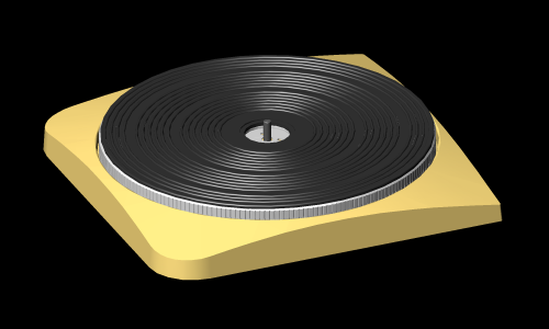
This is the non-magnetic Zamak alloy subplatter from my TD124 Mk II.
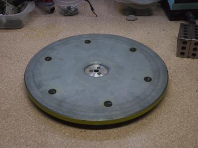
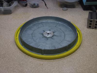
As you can see the outside of the idler ring cannot be used as a belt drive pulley. Many would say that it is useless as a turntable subplatter generally because of high frequency ringing. Kevin calls his "the bell". It was designed for a cheaper turntable but offered to European customers as an option to address the high flux cartridge issue. American customers didn't get any choice. The cheap Zamak subplatters were standard issue on the TD 124 Mk II in the USA.
Apparently.
From the Schopper AG website:
As you can see the outside of the idler ring cannot be used as a belt drive pulley. Many would say that it is useless as a turntable subplatter generally because of high frequency ringing. Kevin calls his "the bell". It was designed for a cheaper turntable but offered to European customers as an option to address the high flux cartridge issue. American customers didn't get any choice. The cheap Zamak subplatters were standard issue on the TD 124 Mk II in the USA.
from post1
does this exist?
Apparently.
From the Schopper AG website:
Non-Magnetic Main Platter

The TD 124 "drive platter", also known as the "main platter" or "sub-platter", is an essential element in the Thorens design concept. Thorens chose cast iron for the TD 124 series due to its outstanding properties: high density and damping capacity, great rigidity and extraordinary dimensional stability. These structural advantages, so important to the Thorens sound, involved one major disadvantage: the platter is magnetic, limiting the choice of cartridge. Heavy cartridges with strong magnets - like the Ortofon SPU - were drawn to the platter by magnetic attraction, sometimes to the point of damaging the cartridge. Tracking force across the platter, and accurate anti-skate was impossible to achieve. To address the problem, Thorens engineers in Sainte-Croix experimented extensively with alternative platter materials. Each of these experiments resulted in a platter which was either prohibitively expensive or sonically inferior to the original formulation. In the mid-60's, for example, Thorens offered on special order a non-magnetic replacement main platter manufactured from pressed aluminum. The platter was produced by Inca, the Swiss foundry that also produced the TD 124 chassis. In addition to the excessively reduced weight (2.8 kg), the platter brought with it distinct sonic disadvantages, namely high-frequency ringing! For this reason the platter was never offered as a standard component in the TD 124 series. Similar problems plagued the lead prototypes that Thorens also experimented with.
The only appropriate material for a sonically superior non-magnetic platter is "grey cast" iron with graphite flakes, a unique compound developed by the US marines for minesweeping operations during World War II. This unique alloy shows a 98% reduction in residual magnetism compared with the standard cast iron, while equaling or bettering it in terms of density, stability and damping properties. At the time, however, high raw material and production costs limited the availability of this material for civilian applications.
Today, however, we can offer a non-magnetic replacement platter weighing 5 kg - nearly the same weight as the original - which surpasses the original in all respects. Our replacement platter is manufactured from raw materials chosen without compromise, followed by state-of-the-art casting, precision machining and finishing and faithful reproduction of the original strobe markings, all carried out by the finest Swiss specialty firms. The new, non-magnetic replacement platter for the Thorens TD 124 Series I and II meshes effortlessly with the original Thorens concept, while offering the advantages of:
- no magnetic influence on cartridge coils or magnets
- exact, reliable anti-skating adjustment now possible
- lower noise floor and radically enhanced dynamics
- greater overall tonal balance and coherence
- extended frequency response
- tighter bass
- no restrictions on cartridge selection
I have both the cast iron platter and the zamac and use three different Ortofon SPU LOMC cartridges with relatively powerful magnets, I have also used DL-103D, and Benz Ebony H MCs with the cast iron platter with no difficulty. I use a digital tracking force gauge to set tracking force with the Schick and clone 3012 arms.
The cast iron platter is much less resonant than the zamac platter and this is audible in direct comparison during playback.
I use the zamac platter on my older TD-124 with a glass top platter and cork applied to the inside of the zamac platter. On top of this is a gem dandy mat.. Works fairly well.
There is also a non-magnetic stainless steel platter from Mirko that is supposed to be good.
The Schopper platter is very good, but also very expensive. I had planned to get one, but so far the oem cast iron platter works just fine for me. Eventually I will get another for the older table.
Doug, keep us up to date on your progress, I for one am very interested in what you are doing.
[]
My first attempt was designed to fit inside the platter idler ring. It required the special pulley which was a PITA because it had to mate to the bottom of the spindle flange yet clear the spindle well flange. Then it had to rise up to clear the Mk II motor mount. I got to thinking that perhaps the outside of the platter idler ring could act as a pulley. I wasn't about to cut into my Thorens chassis, thus the aluminum extrusion. The new motor pulley is about twice the diameter of the first one. Out of sheer luck the I got it to almost perfect size the first try. It hits speed in about 1/4 turn compared to a full turn on X drive 1, even though the belt is 30% narrower and thinner. This is due, I suppose, to the larger pulleys putting less stress on the belt. I'm thinking that perhaps the motor more powerful than necessary.
The drive is really quiet. However, since it is a permanent magnet motor there is vibration due to cogging. I suspect a weaker motor would have weaker magnets and lower vibration levels. This is a 300 RPM motor. Perhaps 600 RPM would be a better choice. The motor pulley would return to the smaller size and the higher RPM might give more torque for the same size motor.
I'm preforming these experiments, not to replace the drive on my TD 124, but to test out ideas for a DIY turntable with features borrowed from Thorens, namely retro design cast aluminum chassis, similar bearing, cast iron platter and improved cueing.
It looks that the Hurst motor is a two phase PM syncmotor, with a phase capacitor for the second phase .
Concerning the vibration have you tried to tune the phase capacitor for a optimum value , with the Thorens TD 160 PM motors I did this it gives a reduction from 8-20 db in vibration on 100 hz (120)
Nice project !
Volken
Thank you.
") Indeed it is a two phase sincro. Hurst makes an extensive line of such. I didn't have a 15mf cap so I'm using a bunch of crossover caps in parallel. It should be easy to test different values, but first I need a zero to low cost way of measuring vibration. Have you any advice? Somewhere on this forum someone mentioned his special VF drive system with "wave shaping." He gave no details. Is this real or snake oil?
Indeed it is a two phase sincro. Hurst makes an extensive line of such. I didn't have a 15mf cap so I'm using a bunch of crossover caps in parallel. It should be easy to test different values, but first I need a zero to low cost way of measuring vibration. Have you any advice? Somewhere on this forum someone mentioned his special VF drive system with "wave shaping." He gave no details. Is this real or snake oil?My concept is to offer the base turntable to run at 33 1/3 RPM with a remote transformer and no electronics. An optional variable frequency drive would be available. In keeping with the retro analog principle I was thinking a wein bridge oscillator with low level phase shifting. A two channel amplifier would drive the 24V motor. There would be strobe markings for 33 1/3 at 60 Hz only. I never cared for the under platter strobe markings on the TD 124. The window breaks up the lines of the chassis. I thought the strobe markings could be pressed into the upper platter edge. The basic model would have no strobe light since the speed can't be adjusted. The variable speed package would have an orange led driven by a quartz oscillator. Rather than having multiple strobe markings the led would flash at different rates for different speeds. I'd like to support 33 1/3, 45 and 78 RPM but I suspect the motor will not run fast enough for 78, especially if I choose 600 RPM. I'm not sure if it is practical to make a mechanical 50 Hz model. The VF drive would provide this accommodation. I'm stronger with mechanics and packaging than I am with electronics. I welcome suggestions and criticism.
I've been going back an forth about what should be drop-in compatible with the TD 124. I'd be nice if the spindle were interchangeable. It's dumb that Schopper only sells theirs with the bearing well since the well never goes bad. I would make a more robust well out of aluminum. It could be integral to the chassis, although in the prototype it would have to be separate since the chassis is too large to turn on my machine. I'll use the Thorens well. I would like to have my subplatter useable on the TD 124. Presumably, if produced in production volumes it could seriously undercut Schopper, although I haven't figured out how to print the strobe markings. The upper platter should be interchangeable and of similar design but that's only possible with production tooling. The mat is DIYable. I have experience making molds for and casting urethane. I love the satin chrome 45 center adapter but that probably impractical for the prototype. The chassis would pay homage to, but not duplicate the TD 124. It would have the same geometry and footprint but it would not have the arm board bracket. Tonearms would be mounted to the plinth but a spacer would be available so TD 124 arm boards could be used. The TD 124 cueing mechanism is a little flawed. It's easy to jostle the table when engaging it. I've come up with a cam system that operates with a lever from the side, like a traditional arm lift. There would be no speed selector on the chassis, that's where my monogram would be cast. I would like to have the bubble level double as a push on push off power button. It would be cool if instead of a simple circle on it there was the broken circle with vertical line. In other words the international power button symbol.
Anyway, here is a concept drawing:
Today I cobbled a variable frequency drive out of a Kenwood power amp (only one channel working.) hooked up to my old Wavetek. I was surprised that it was able to spin the TT as high as 96 RPM. At each speed I adjusted the cap value to attain a 90 degree phase shift. (As observed on an analog scope.)
I found that at 33 1/3 RPM the cap wanted to be 12mf. At 45 RPM 6mf. At 78 RPM 2mf. Even at this lo value the shift was not 90 degrees but it wouldn't work reliably with less capacitance.
This is encouraging. I didn't think I'd go that fast. I guess I'll pass on the 600 RPM motor idea. The motor wouldn't start at increased RPM but that should not be a problem. The real VF drive could ramp up to speed. I also found that often, even at 33 1/3 RPM, when the start up delay/speaker protection relay kicked in it would kick right out. It might click several times before the motor started. I suspect the motor presents a very low impedance until it gets going.
So, what should I be looking for in a motor drive amp? 24V RMS puts 72 watts into 8 ohms, but the motor only consumes 7.5 watts. Regardless, the amp would need greater than +/- 20V supplies. The maximum necessary frequency is less than 150 Hz. Does this simplify the design or would it still have to be a broadband amp? Is a motor tougher to drive than a speaker?
Low frequency that ramps up to final speed.
That's the plan. Start at 33 1/3 which is the motor's rated RPM of 300 then ramp up the frequency and back off the phase shift.
Except transformers ramp up in one cycle. All you need is a zero crossing detector and triac to tame them. The motor's impedance won't go up until it gets moving.Motors are like transformers.
High start up currents.
Start at ~1/5 of the motor's nominal frequency and ramp up this frequency over a period of one to two seconds, to the motors nominal operating frequency.
If you require very high frequency operation for the higher speeds of 45 & 78, then you still need to start from the ~10Hz or so, to get the motor running without drawing excessive current from the driving amplifier. Had you used mains or a transformer as the drive, the source tolerates the high starting current.
If that is too complicated then use low starting voltage, again ramping over 1 to 2 seconds. You have the heavy platter that is a very heavy load on the motor as it "TRIES" very hard to accelerate up to speed and this needs lots of current.
Remember that output torque is proportional to motor current.
Last edited:
Not motor impedance............. The motor's impedance won't go up until it gets moving.
It's the motors back emf.
The back emf is proportional to motor speed.
At zero speed there is zero back emf.
At full speed the back emf is almost exactly equal to the supply voltage.
The very slight difference is the net driving voltage.
That net driving voltage divided by the motor impedance (mostly resistance) resulting in the no output torque (frictional losses only) operating current.
Slow the motor slightly, or in a synchronous motor run it slightly out of phase, and the back emf drops to then allow an increase in motor current to flow and thus give a useful output torque.
a bit more than that, 3 to 5 cycles to stabilise to final quiescent current......................
Except transformers ramp up in one cycle..................
The inertia of the platter and to a lesser extent the inertia of the rotor are equivalent to the capacitor bank added to the rectified transformer output................... You have the heavy platter that is a very heavy load on the motor as it "TRIES" very hard to accelerate up to speed and this needs lots of current................
You need current to get the transformer or motor started.
You need continued current to drive the connected load (charging the capacitors, or accelerating the platter).
Last edited:
Exactly, It doesn't matter how slow you ramp up the voltage or frequency. The load won't decrease till you get the sucker moving. The amp will have to deliver the current, if only for a moment. The platter isn't much of an issue, the light, relatively loose belt allows plenty of momentary slip.
You only need to tame the first cycle of a transformer to keep it from making that annoying thump.
You only need to tame the first cycle of a transformer to keep it from making that annoying thump.
The power amplifier in fact may not like the motor inductance during start up, a number of my friends are power systems engineers who work on motor drives - in fact I am building a 3 phase 120V drive for my Papst. Their recommendation is a zobel network with 1 - 2.2uF of capacitance and a resistance close to what the manufacturer recommends for a standard zobel (series RC) network on the output (perhaps 1 - 4 ohms).
A small amount of resistance in series with the load may help as well.
I will report back on my drive debug as things start to come together.
A small amount of resistance in series with the load may help as well.
I will report back on my drive debug as things start to come together.
Do you want to reduce the intolerance to high start up current?Exactly, It doesn't matter how slow you ramp up the voltage or frequency. The load won't decrease till you get the sucker moving. The amp will have to deliver the current, if only for a moment. The platter isn't much of an issue, the light, relatively loose belt allows plenty of momentary slip.
You only need to tame the first cycle of a transformer to keep it from making that annoying thump.
Then you need to do something to increase the tolerable output current of the drive amplifier
or
reduce the current draw during start up.
Kevin, is your Papst drive to be VF? Will it use a 3 channel amp or phase shift caps on the output. Will it put out 117 VAC directly, or through a step up transformer? Can't wait to see the result.
From your discription it sounds like the capacitor and resistor are in series, yes? Is the network in series with the load or parallel? You said the capacitor should be close to the manufacturer's recommended value. Do you mean the recommended phase shift cap value?
I was grossly off in my guesstimation of the required amplifier output voltage. To achieve 24V RMS I need 68V peak to peak. That means supply rails exceeding +/- 35V.
I did some additional testing. I reduced the direct transformer output to 20VAC and the motor ran fine. Emboldened, I hooked it up to an LM3886 chip amp that puts out 16.6VAC. The motor buzzes for a fracrion of a second then takes off. The platter reaches speed in less than 1/2 turn at 33.3 RPM. It easily runs at 45 RPM but poops out around 60. The amplifer's heat sink remains barely above ambient temperature. More interestly the motor remains cool as well. At 24V it got as hot as my Mk I E50 motor. It would appear that amplifer output current may not be such an issue unless there is a sustained short or something prevents the motor from turning. The Kenwood's speaker protection circuit is likely too fast or sensitive for the unusual load. Now I just need an amp circuit that puts out 24VAC. Couldn't resistors be placed in series with each output transistor to protect the amplifier from the momentary current surge, and a slow blow fuse to protect against a sustained short?
Another observation: When driven directly off the transformer the sine wave is quite distorted. With the amp and function generator the wave is visually very clean, even on the phase shifted coil.
Last edited:
Once you get that 3 phase power supply working, some of us might be interested in building one also
The power amplifier in fact may not like the motor inductance during start up, a number of my friends are power systems engineers who work on motor drives - in fact I am building a 3 phase 120V drive for my Papst. Their recommendation is a zobel network with 1 - 2.2uF of capacitance and a resistance close to what the manufacturer recommends for a standard zobel (series RC) network on the output (perhaps 1 - 4 ohms).
A small amount of resistance in series with the load may help as well.
I will report back on my drive debug as things start to come together.
- Home
- Source & Line
- Analogue Source
- Restoring and Improving A Thorens TD-124 MKII