Hi!
I have a fw audio interface with RIAA stage in-build.
Problem is that the RIAA EQ it's not OK.
Here's a graph showing the eq curve this stage produces (sorry 'out the weak resolution):
Since 'error' is in both channels, that would tend to indicate a bad design, or more likely, the wrong filter components were installed during manufacture?
Is it just treble roll-off 'stage' (2122Hz) missing or, is the bass turnover 'stage' (~500Hz) missing as well?
Juha
I have a fw audio interface with RIAA stage in-build.
Problem is that the RIAA EQ it's not OK.
Here's a graph showing the eq curve this stage produces (sorry 'out the weak resolution):
An externally hosted image should be here but it was not working when we last tested it.
Since 'error' is in both channels, that would tend to indicate a bad design, or more likely, the wrong filter components were installed during manufacture?
Is it just treble roll-off 'stage' (2122Hz) missing or, is the bass turnover 'stage' (~500Hz) missing as well?
Juha
Before condemning the circuit, make sure you aren't overdriving it. These circuits work down to microvolts so it doesn't take much to overdrive and get erroneous response curves.
Originally I noticed the problem through listening and not through measure.
My cartridge Output voltage is: 2.0mV, 1kHz , 5cm/s to zero peak, lateral velocity (5.6mV, 1kHz, 10cm/s, zero to peak, 45° velocity (DIN45500)).
If the cartridge output voltage is too high for ESI phono input then, shouldn't there be hearable distortion in playback? There isn't.
Here is a sample recorded through this ESI device and another for comparison sake:
ESI DuaFire 16/44.1 02_DS_WDYTYG_DuaFire.wav ( 5.08MB )
Terratec iVinyl 16/44.1 04_DS_WDYTYG_iVinyl.wav ( 5.08MB )
BTW, when I measured this device using RMAA software, I got warning of high (>6%) distortion so, it's possible that curve in graph isn't fully valid. I also measured another RIAA pre-amp and got same warning but the RIAA eq curve looked follow the standard.
Juha
Looks like no hf rolloff.
That's my thought as well but, IMO, by the picture, there's some roll-off berween frequency range 500Hz-5kHz. If the 2122Hz roll-off is missing totally then shouldn't the curve be turning more upwards after ~1kHz?
Juha
If the 2122Hz roll-off is missing totally then shouldn't the curve be turning more upwards after ~1kHz?
No, probably not. The zero at ~500Hz will just cause the response to flatten out, which it sorta does. I think John's right here, either the pole at 2122Hz is missing or it's in the wrong place (possibly a cap or resistor value off by a decade), ASSUMING the response curve you're showing is correct. If there really is high distortion, all bets are off and you need to concentrate on fixing that issue first.
No, probably not. The zero at ~500Hz will just cause the response to flatten out, which it sorta does. I think John's right here, either the pole at 2122Hz is missing or it's in the wrong place (possibly a cap or resistor value off by a decade), ASSUMING the response curve you're showing is correct. If there really is high distortion, all bets are off and you need to concentrate on fixing that issue first.
Distortion was in measure only (I suppose it came because of wrong method I used (RMAA loopback test where E-MU 0404 USB output fed the ESI phono input --> too high output level after RIAA stage)).
So, I need to open the case (again) and try to
- find the values of resistors/caps used in RIAA stage and
- solve the stage schematic
Juha
BTW, here's maybe a better picture showing the 'error' in curve (30s sweep from 5 to 22.05kHz):
An externally hosted image should be here but it was not working when we last tested it.
Last edited:
Missing edit button.
Tracing the circuit is not an easy task for me but, hey, here are the pictures showing stage compnents. I quess the RIAA stages are just after the phono input ports?
1st picture shows the connectors on rear panel.
2nd picture shows the uper side of the board.
3rd picture shows the other side of the board.
1. http://img39.imageshack.us/img39/5894/esiinpsw.jpg
2. http://img826.imageshack.us/img826/7079/06082010566.jpg
3. http://img251.imageshack.us/img251/5931/06082010570.jpg
Values of most of those tiny components can be seen on those attached pictures. Is it possible to tell by the pictures if there are something on those components (values/placing/...) which might be the reason for this issue in question (I don't have equipment other than an old multimeter which I could use for to measure resistors, and I think if I take some that tiny parts off from there I can't get them back again with my 500W soldering iron )?
)?
(I took those two pictures using mobilephone camera so, the quality of takes isn't best possible).
Juha
Tracing the circuit is not an easy task for me but, hey, here are the pictures showing stage compnents. I quess the RIAA stages are just after the phono input ports?
1st picture shows the connectors on rear panel.
2nd picture shows the uper side of the board.
3rd picture shows the other side of the board.
1. http://img39.imageshack.us/img39/5894/esiinpsw.jpg
2. http://img826.imageshack.us/img826/7079/06082010566.jpg
3. http://img251.imageshack.us/img251/5931/06082010570.jpg
Values of most of those tiny components can be seen on those attached pictures. Is it possible to tell by the pictures if there are something on those components (values/placing/...) which might be the reason for this issue in question (I don't have equipment other than an old multimeter which I could use for to measure resistors, and I think if I take some that tiny parts off from there I can't get them back again with my 500W soldering iron
)? (I took those two pictures using mobilephone camera so, the quality of takes isn't best possible).
Juha
It looks like the 75us pole is there, but closely followed by a zero at about 50us. Is the non-inverting opamp circuit hitting its minimum unity gain at far too low a frequency? This would happen if the resistor from -ve input to ground is too large
Hmm... do you mean
- the JRC4580 op-amp near the line/phono switch (picture 2) or another op-amp found some other position (there are few of those onboard)?
- case of resistot R1 in picture ?
An externally hosted image should be here but it was not working when we last tested it.
Juha
That right, there should be a complex network of Rs and Cs in place of R2 in your circuit, which give the 3180 & 75us pols and the 318us zero.
R1 is likely to have an electrolytic in series to reduce dc gain to unity.
If R1 is too big, you would expect overall low gain and the hf boost you are getting
R1 is likely to have an electrolytic in series to reduce dc gain to unity.
If R1 is too big, you would expect overall low gain and the hf boost you are getting
Thanks!
I need to get better equipment (multimeter to measure capacitence values) to get those checked.
Value of R107 (if it's part of the R1 circuit) isn't very big so, if there's a 100μF condencator in series with it, deoes it mean that it's not root for the issue or, do I just have to make it less?
Are those caps C62/C63 and C69/C70 (picture #2) part of the RIAA circuit since, If I see it right, either R118/R111 or R117/R110 are connected with them?
Juha
Return to the topic... 
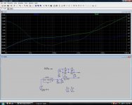
OK, I did a LTSpice schematic for the RIAA stage of DuaFire.
Measured those R's and C's David mentioned and those were OK. As picture shows, in theory, removing the R112 makes curve look quite good but, in practice, it didin't lead to situation which simulation shows (so I quess there must be more components involved).
Wondering, where to look next?
OK, I did a LTSpice schematic for the RIAA stage of DuaFire.
An externally hosted image should be here but it was not working when we last tested it.
Measured those R's and C's David mentioned and those were OK. As picture shows, in theory, removing the R112 makes curve look quite good but, in practice, it didin't lead to situation which simulation shows (so I quess there must be more components involved).
Wondering, where to look next?
I ran a simulation of the circuit myself, but with an inverse RIAA input so the response cure ideally would be a straight line. The circuit as it is given is anything but a correct RIAA response. Not sure what the 15K resistor is doing in this circuit; nearly all single op amp phono stage circuits I have seen do not have a resistor in series with the RIAA network in the feedback arm. Secondly, the values for the RIAA network are a bit off. I recalculated the RIAA network values, got rid of the 15K resistor, and added a low-pass filter on the output to cancel the unwanted zero in the response due to op amp gain being unable to fall below unity in a series feedback circuit such as this. Lastly, the 47µF capacitor has been changed to 470µF to reduce the amount of distortion that would otherwise be present at low frequencies. Better to perform subsonic filtering with a separate stage designed for the purpose than to rely on a wide tolerance and potentially high-distorting electrolytic capacitor. The simulation results and .asc files are attached.
Attachments
...
Not sure what the 15K resistor is doing in this circuit; nearly all single op amp phono stage circuits I have seen do not have a resistor in series with the RIAA network in the feedback arm. Secondly, the values for the RIAA network are a bit off.
...
I recalculated the RIAA network values, got rid of the 15K resistor, and added a low-pass filter on the output to cancel the unwanted zero in the response due to op amp gain being unable to fall below unity in a series feedback circuit such as this.
...
Thanks!
I noticed that the C1 and C2 are little off in my linked schematic but, as the edit button isn't active after a while here... .
Could it be possible that the 15K resistor is just totally off as mentioned earlier? About the same time when I started this thread I took contact to ESI to get some schematics for the RIAA stage but they just send me specs for the phono amplier.
By following David's suggestion, R112 changed to 150R gives better responce in practice as well but ... still not enough low frequencies and peaks start to clip a bit. When totally remove the R112 then the gain is just too high.
I'll check if your suggestion helps in this.
Is there any limit for load capacitance value?
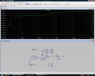
By simulation (if I have done everything right), original RIAA circuit could be left untouched by just dropping the input capacitance down to 33pF (original value is 150pF and both cardridges I use say it should be less than 200pF). Would this be wrong way to go? If the schematic/simulation is done wrong, could you assist ...
Cartridge specs:
DC resistance 500ohm
Inductance 240mH
Impedance 1.6kohm 1kHz
Recommended load 47kohm
Recommended load capacitance <200pF
By simulation (if I have done everything right), original RIAA circuit could be left untouched by just dropping the input capacitance down to 33pF (original value is 150pF and both cardridges I use say it should be less than 200pF). Would this be wrong way to go? If the schematic/simulation is done wrong, could you assist ...
An externally hosted image should be here but it was not working when we last tested it.
Cartridge specs:
DC resistance 500ohm
Inductance 240mH
Impedance 1.6kohm 1kHz
Recommended load 47kohm
Recommended load capacitance <200pF
- Status
- This old topic is closed. If you want to reopen this topic, contact a moderator using the "Report Post" button.
- Home
- Source & Line
- Analogue Source
- RIAA stage problem ...