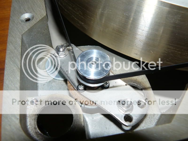
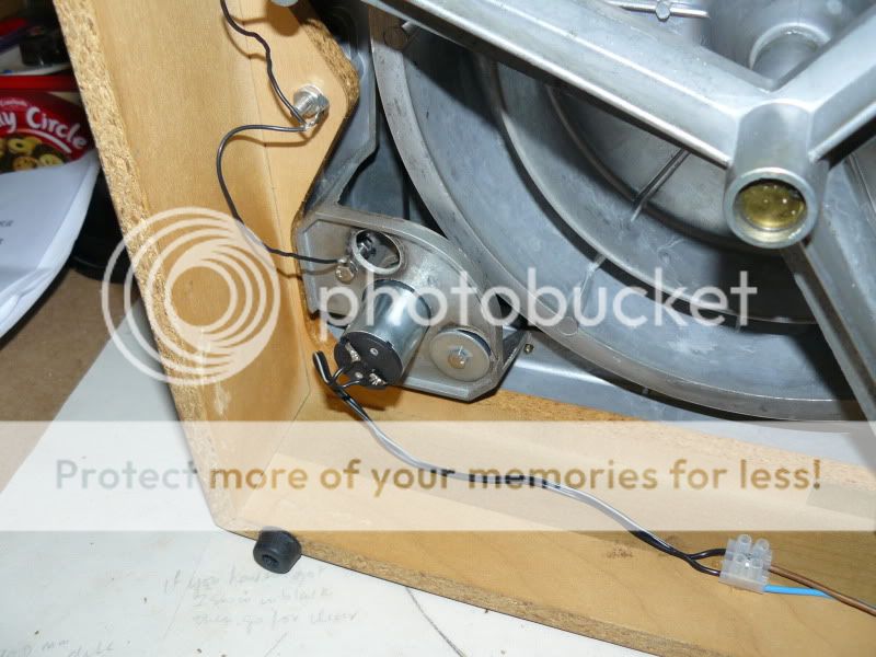
Even that isn't a good solution, as most inverters are not frequency stable. I would first get a step down transformer to bring the power down to about 100V (with consideration for the lower frequency). Then change the diameter of the motor pulley - it's too small for 50 Hz. (I assume this is either belt or idler driven, not direct drive.)
Measure the pulley with a micrometer and make a sleeve for it that is as close as you can get to 6/5 the diameter. You will now have a working setup, but with two down sides - the torque will be lower due to the lower mains supply, and you will get a bit more wow and flutter if your sleeve isn't perfectly true to the rotational center.
Measure the pulley with a micrometer and make a sleeve for it that is as close as you can get to 6/5 the diameter. You will now have a working setup, but with two down sides - the torque will be lower due to the lower mains supply, and you will get a bit more wow and flutter if your sleeve isn't perfectly true to the rotational center.
Hm, That might work. It is a belt drive.
I might be able to get a custom pulley turned at work. By talking nice to the mechanic.
As far as torque and power at 50Hz I need to enlist the enlightened ones here at the forum. I don´t understand how you arrive at 100v instead of 115V
Here is another way of solving the problem, by Mark Kelly, but I can not find any schematic.
ClariSonus - Clear and enjoyable sound Mark Kelly on Empire Motor Project, part 1
Mark Kelly's solution requires a 60 Hz oscillator, again with the stability issues I mentioned.
The reason I suggest 100V rather than 115V is that, due to the lower frequency, you might be flirting with core saturation. Reducing the voltage to 100 will avoid that. Of course you could try it at 115 if you monitor the line current carefully but at least be aware of the potential problem. The flux density is proportional, sort of, to the excitation voltage and inversely proportional to the excitation frequency. If you lower one you must lower the other to maintain flux density.
The reason I suggest 100V rather than 115V is that, due to the lower frequency, you might be flirting with core saturation. Reducing the voltage to 100 will avoid that. Of course you could try it at 115 if you monitor the line current carefully but at least be aware of the potential problem. The flux density is proportional, sort of, to the excitation voltage and inversely proportional to the excitation frequency. If you lower one you must lower the other to maintain flux density.
I agree with the 100 volts, 60Hz motors often take a big surge and start abnormally fast when run on 50Hz at their nominal voltage. Papst motors often have phase splitting caps, if so the value should be increased by about 20 percent, this will increase the torque though generally these motors are torquier at 50Hz anyway. Torque is unlikely to be a problem although you will need more with the larger mptor pulley. Some one who has access to Empire spares may already have a 50Hz pulley.
If you want an accurate 50 Hz voltage the best way is to start with an xtal oscullator driving a PLL synthesizer chip to generate a supermultiple of 50 Hz, say 50Hz*256. Then use this signal to drive a counter which accesses a sinewave look-up table. The lookup table drives a D/A converter and a low voltage amplifier capable of producing 10-20 VRMS. All that needs to be done then is use a stepdown transformer wired bakcwards to get the desired voltage. This approach is stable to the tolerance of the cxtal, typically a few hundred PPM. Most of the functions I have described above are available in an integrated device, so the parts count need not be that high.
Here is a simpler way to achieve the same goal: using a counter, divide an xtal frequency down to yield a 50 Hz square wave and then low pass filter it to remove the upper harmonics. I have implemented this approach using a 3-pole Sallen-Key lowpass filter; it yielded <5% THD on the sine wave. The amplitude tolerance will be limited by the Vdd tolerance (assuming rail-rail CMOS output swing on the counter).
Mark Kelly's solution requires a 60 Hz oscillator, again with the stability issues I mentioned.
Not so, that RC oscillator has demonstrated better than 100 ppm stability in use. This seems to be adequate in practice. That stability was achieved by using capacitors and resistors which have complementary TCs and by stabilising the oscillator temperature.
Measure the pulley with a micrometer and make a sleeve for it that is as close as you can get to 6/5 the diameter.
The ratio of pulley diameter to platter diameter is not the simple ratio you assume, it depends on belt thickness. To get the correct pulley diameter you would need the new pulley to equal 1.2 x old pulley diameter + 0.2 x belt thickness.
barrymagrec said:Papst motors often have phase splitting caps, if so the value should be increased by about 20 percent
That's not correct, the frequency for correct phase shift is proportional to 1 / SQRT (LC). Since L is fixed by the motor winding inductance a 20% frequency shift requires about 40% change in C.
The easy explanation for voltage variation: these motors have a back EMF which is proportional to drive frequency and you want to maintain the original margin between drive voltage and back EMF. A decent rule of thumb for the Empire motor: The back EMF is volts is roughly equal to the drive frequency in Hz, so if you decrease the frequency by 10 Hz drop about 10 V off the drive voltage.
Last edited:
If you want an accurate 50 Hz voltage the best way is to start with an xtal oscullator driving a PLL synthesizer chip to generate a supermultiple of 50 Hz, say 50Hz*256. Then use this signal to drive a counter which accesses a sinewave look-up table. The lookup table drives a D/A converter and a low voltage amplifier capable of producing 10-20 VRMS.
For someone whose moniker is "analog_guy" that's terribly digital.
 It's perfectly possible to make a nice stable analogue oscillator to drive turntables - just avoid the thermistor stabilised Wien bridge (high distortion at low frequencies).
EC8010,
You do have a point, both regarding my choice of circuits and my moniker. My concern with a Wien bridge is component accuracy. Trimming is possible, but two of the bridge resistors must track.
Most of the circuits I design for my day job are in the 4-8 GHz range, where everything ALL circuits appear analog and all interconnects behave as t-lines.
Yes, once you go up in frequency, even digital becomes analogue. As you say, analogue oscillators usually require two variable components to track, but that's less of a problem than at first appears. We don't need much variation; +/-6% (half a semitone) is all we need, so the proportion of the total frequency-setting resistance that needs to be variable is only 12%. Secondly, linear variable resistors generally do track quite well. Thirdly, tracking errors only cause an amplitude error, typically 1%, which is irrelevant for a motor. As proof that it can be done, here's the oscillator I use (plus some bells and whistles to generate three phases - just take the cosine output for a simple motor):
Attachments
The trouble with all these solutions is that they are complex. Some require special parts. Unless you are a purist, you don't need to go to such lengths to make your turntable run at the correct speed.
I am in favor of the replacement spindle (or sleeve over the present one). The power line voltage is easily resolved with a transformer or, if you really want to get crude, a dropping resistor.
I am in favor of the replacement spindle (or sleeve over the present one). The power line voltage is easily resolved with a transformer or, if you really want to get crude, a dropping resistor.
The trouble with all these solutions is that they are complex.
Well, yes. That's because the alternative is precision machining. I have a lathe but I doubt very much that I could make a sleeve to the precision required. By comparison, soldering a few components onto stripboard and throwing it all in a box requires commonly available tools and only a little care.
Many years ago I owned an Empire turntable, and if I remember correctly the drive to the belt came directly from a brass spindle with a convex cross section to keep the belt centered. There are only two precision dimensions that need be considered: the ID that fits onto the motor shaft and the OD that contacts the belt. If the ID is a standard size it is possible to get a very good fit using an appropriately sized reamer. The OD can be cut and measured with a micrometer. I have a nice German lathe which can hold .001" with no difficulties.
I have a nice German lathe which can hold .001" with no difficulties.
Likewise. However, although I can machine a dimension to about 0.00025" if I really try, it will always have a measurable taper because of imperfections in the alignment between the headstock and tailstock, and that makes it difficult to drill and ream a hole that is concentric with the outer machined surface. One possible solution is to do the hole, remove the work, then machine a shaft that fits tightly in that hole, keep the shaft in the lathe, slip the first piece of work over the shaft, and machine the outside to make the pulley.
The very first (broadcast) video tape machines used 2" tape, a lot of precision mechanical parts, and a vacuum system. As electronics improved, less and less mechanical precision was needed because errors could be compensated for in the electronics. Eventually, it became possible to record video mostly with bits of pressed steel and moulded plastic (plus a lot of cheap electronics). That principle still holds; it's almost always easier to avoid precision mechanical engineering by adding some electronics.
- Status
- This old topic is closed. If you want to reopen this topic, contact a moderator using the "Report Post" button.
- Home
- Source & Line
- Analogue Source
- Help I bought a Empire turntable for 115V 60Hz in a 240v50Hz country